tekmar 270 Boiler Control User Manual
Page 15
15 of 24
© 2010 D 270 - 08/10
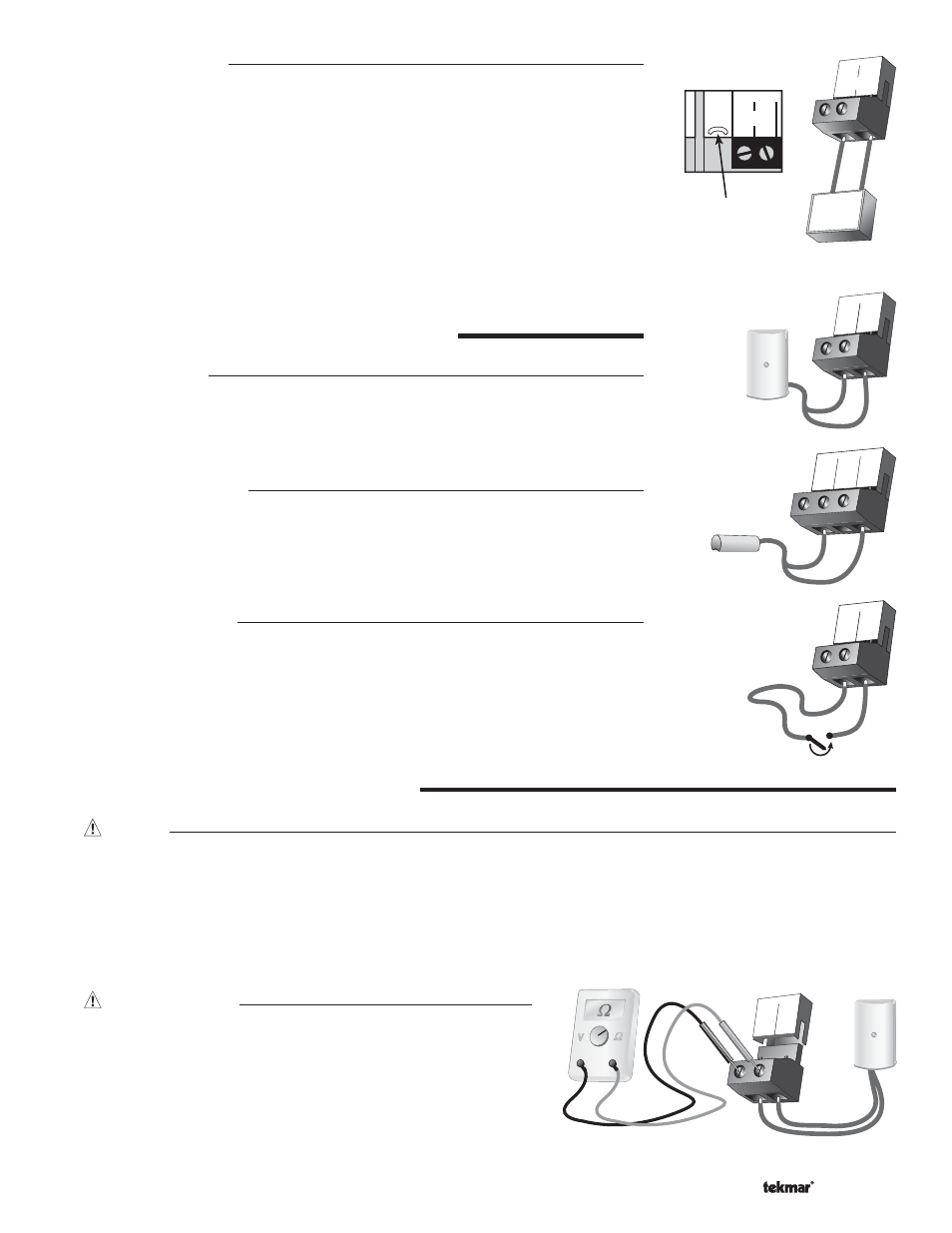
Modulation Output
The Modulation Output terminals (11 and 12) provide a 0 to 10 V (dc) or a 2 to 10 V (dc)
output to the boiler. If a 0 to 20 mA or a 4 to 20 mA output is required, cut the jumper wire
located next to the modulation output.
The modulating outputs replace any mechanical operator such as a T991. Observe
polarity when connecting the control to the boiler.
SENSOR AND UNPOWERED INPUT CONNECTIONS
Do not apply power to these terminals as this will damage the control.
Outdoor Sensor
Connect the two wires from the Outdoor Sensor 070 to the Com and Out terminals (17 and
16). The outdoor sensor is used by the control to measure the outdoor air temperature.
Boiler Supply Sensor
Connect the two wires from the Boiler Supply Sensor 082 to the Com and Boil terminals
(13 and 15). The boiler supply sensor is used by the control to measure the boiler supply
water temperature.
UnOccupied Switch
If an external timer (tekmar Timer 032) or switch is used, connect the two wires from the
external switch to the Com and UnO Sw terminals (13 and 14). When these two terminals
are shorted together, the control registers an unoccupied (UNOCC) signal.
Connection to Operate
Modulating Boiler
11
+
12
–
Mod V (dc)
+
–
V (dc)
STEP FIVE
——————
TESTING THE WIRING
General
Each terminal block must be unplugged from its header on the control before power is applied for testing. To remove the terminal
block, pull straight down from the control.
The following tests are to be performed using standard testing practices and procedures and should only be carried out by
properly trained and experienced persons.
A good quality electrical test meter, capable of reading from at least 0 to 300 V (ac) and at least 0 to 2,000,000 Ω, is essential to
properly test the wiring and sensors.
Test The Sensors
In order to test the sensors, the actual temperature at each sensor
location must be measured. A good quality digital thermometer with
a surface temperature probe is recommended for ease of use and
accuracy. Where a digital thermometer is not available, a spare sensor
can be strapped alongside the one to be tested and the readings
compared. Test the sensors according to the instructions in the Data
Brochure D 070.
17
Com
16
Out
13
Com
14
UnO
Sw
15
Boil
13
Com
14
UnO
Sw
Timer Switch
17
Com
16
Out
11
+
--
12 1
Mod V(dc) C
*
Cut jumper
for 0-20 mA
or 4-20 mA