tekmar 270 Boiler Control User Manual
Page 14
© 2010 D 270 - 08/10
14 of 24
5
6
115 V (ac)
L
N
Power
L
N
1
2
Boil
Dem
Com
Dem
24 to 230 V (ac)
N
L
2
3
Com
Dem
DHW
Dem
24 to 230 V (ac)
N
L
L
115 V (ac)
N
Prim
P1
Power
L
6
N
4 5
7 8
M
24 to 230 V (ac)
DHW
Pmp/Vlv
or
N
L
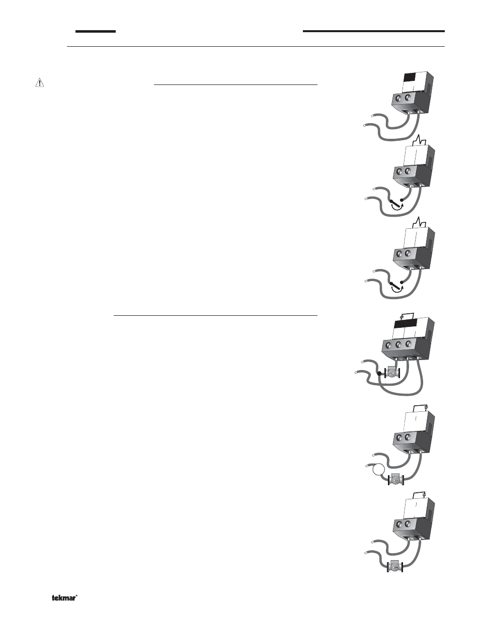
STEP FOUR
ELECTRICAL CONNECTIONS TO THE CONTROL
General
The installer should test to confirm that no voltage is present at any of the wires. Push the control into the base and slide it down
until it snaps firmly into place.
Powered Input Connections
115 V (ac) Power
Connect the 115 V (ac) power supply to the Power L and Power N terminals (5 and 6).
This connection provides power to the microprocessor and display of the control.
As well, this connection provides power to the Prim P1 terminal (4) from the Power L
terminal (5).
Boiler Demand
To generate a Boiler Demand, a voltage between 24 V (ac) and 230 V (ac) must be
applied across the Boil Dem and Com Dem terminals (1 and 2).
DHW Demand
To generate a DHW Demand, a voltage between 24 V (ac) and 230 V (ac) must be
applied across the Com Dem and DHW Dem terminals (2 and 3).
Caution: The same power supply must be used to power both the DHW Demand and
the Boiler Demand circuits since they both share the Com Dem terminal.
Output Connections
Primary Pump Contact (Prim P1)
The Prim P1 output terminal (4) is a powered output. When the relay in the control
closes, 115 V (ac) is provided to the Prim P1 terminal (4) from the Power L terminal (5).
To operate the primary pump, connect one side of the primary pump circuit to terminal 4
and the second side of the pump circuit to the neutral (Power N) side of the 115 V (ac)
power supply.
DHW Pmp / Vlv Contact
The DHW Pmp / Vlv terminals (7 and 8) are an isolated output. There is no power
available on these terminals from the control. These terminals are to be used as a
switch to either make or break power to the DHW pump or the DHW valve. Since this
is an isolated contact, it may switch a voltage between 24 V (ac) and 230 V (ac).
Boiler Pmp P2 Contact
The Boiler Pmp P2 terminals (9 and 10) are isolated output in the control. There is no
power available on these terminals from the control. These terminals are to be used
as a switch to either make or break power to a boiler pump. Since this is an isolated
contact, it may switch a voltage between 24 V (ac) and 230 V (ac).
10
9
24 to 230 V (ac)
L
N
Boiler
Pmp P2