tekmar 265 Boiler Control User Manual
Page 7
7 of 36
© 2010 D 265 - 07/10
To calculate the Minimum Modulation, use the following formulae:
For 4 to 20 mA:
Minimum Modulation = 4 mA – Boiler’s Minimum Input Signal x 100%
4 - 20 mA
For 0 to 10 V (dc):
Minimum Modulation = 0 V (dc) – Boiler’s Minimum Input Signal x 100%
0 – 10 V (dc)
For 2 to 10 V (dc):
Minimum Modulation = 2 V (dc) – Boiler’s Minimum Input Signal x 100%
2 – 10 V (dc)
Example 1:
A boiler requires a 1.8 V (dc) signal to fire the boiler at low fire. The boiler can be modulated to 10 V (dc) where it reaches high fire.
This means the boiler’s input signal range is 1.8 to 10 V (dc). The 265 control has an output signal range of 0 to 20 mA which can be
externally converted to 0 to 10 V (dc) using a 500 Ω resistor (Refer to Modulation Output section in Step 4 of the Installation section).
To make the two signal ranges the same, the Minimum Modulation required is:
Minimum Modulation = 0 V – 1.8 V x 100% = 18%
0 V – 10 V
Example 2:
If the boiler’s input signal range is 6 to 20 mA the required Minimum Modulation is:
Minimum Modulation = 4 mA – 6 mA x 100% = 13%
4 mA – 20 mA
MAXIMUM MODULATION
The maximum modulation defines the maximum output signal from the control to the boiler burner. It is based on a percentage of
the control’s output signal range.
The maximum modulation setting for boilers with power burners is typically set to 100%.
For boilers with electronic operators, the boiler’s input signal range may not match the output signal range of the 265 control. The
Maximum Modulation setting limits the control output range in order to match the boiler’s input range.
To calculate the Maximum Modulation, use the following formulae:
For 4 to 20 mA:
Maximum Modulation = 4 mA – Boiler’s Maximum Input Signal x 100%
4 – 20 mA
For 0 to 10 V (dc):
Maximum Modulation = 0 V (dc) – Boiler’s Maximum Input Signal x 100%
0 – 10 V (dc)
For 2 to 10 V (dc):
Maximum Modulation = 2 V (dc) – Boiler’s Maximum Input Signal x 100%
2 – 10 V (dc)
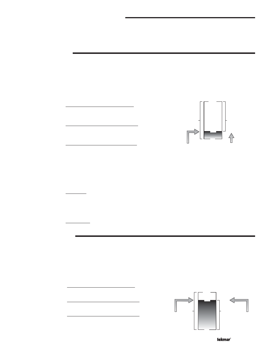
MINIMUM MODULATION
18%
0%
0 V (dc)
1.8 V (dc)
100%
10 V (dc)
10 V (dc)
Control's
Output
Signal
Range
Minimum
Modulation
Boiler's Minimum
Input Signal
Boiler's
Input
Signal
Range
MODULATION RANGE (4 to 20 mA or 0 to 20 mA)
The modulation output (Mod 1, Mod 2, and Mod 3) for each boiler can be adjusted from a 4 to 20 mA output range to a 0 to 20 mA
output range using the Boil Modulation 1, Boil Modulation 2, or Boil Modulation 3 setting. The resulting modulation output signal
can be converted to a 0 to 5 V (dc), 1 to 5 V (dc), 0 to 10 V (dc), and 2 to 10 V (dc) output using external resistors. The modulation
output signal can be converted to a 0 to 135 Ω (W R B) output using a 0 - 135 Ω Converter 005. Refer to the Modulation Output
section in Step 4 of the Installation section.
MINIMUM MODULATION
The minimum modulation defines the minimum output signal from the control to the boiler burner. It is based on a percentage of
the control’s output signal range.
The minimum modulation setting for boilers with power burners is typically set to 0%.
For boilers with electronic operators, the boiler’s input signal range may not match the output signal range of the 265 control. The
Minimum Modulation setting limits the control output range in order to match the boiler’s input range.
MAXIMUM MODULATION
88%
0%
2 V (dc)
2 V (dc)
100%
10 V (dc)
9 V (dc)
Control's
Output
Signal
Range
Maximum
Modulation
Boiler's
Maximum
Input Signal
Boiler's
Input
Signal
Range