tekmar 265 Boiler Control User Manual
Page 21
21 of 36
© 2010 D 265 - 07/10
15 16
M
24 to 230 V (ac)
or
Low Voltage Alert
C.A. /
Alert
23 24
Boiler
Pump 1
24 to 230 V (ac)
21 22
Boiler 3/
DHW
24 to 230 V (ac)
17 18
Boiler
1
1
Connection to Operate
a 4 - 20 or 0-20 mA Device
+
–
4-20 or 0-20 mA
Actuating Motor
6
+
7
–
Mod 1 mA
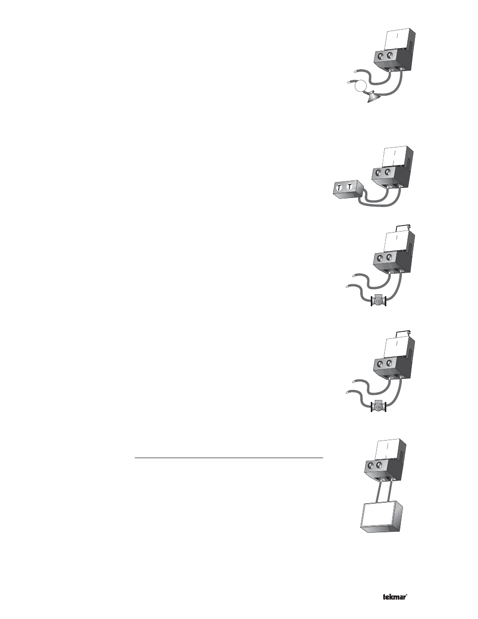
Combustion Air / Alert Contact (C.A./Alert)
The Combustion Air / Alert Contact (C.A. / Alert) terminals (15 and 16) are an isolated
output in the control. There is no power available on these terminals from the control.
These terminals are to be used as a switch to either make or break power to the com-
bustion air damper or alert. Since this is an isolated contact, it may switch a voltage
between 24 V (ac) and 230 V (ac).
Boiler 1 and Boiler 2 Contacts
The Boiler 1 and Boiler 2 terminals (17 and 18, 19 and 20) are isolated outputs in
the control. There is no power available on these terminals from the control. These
terminals are to be used as a switch to enable the modulating boiler. Since this is an
isolated contact, it may switch a voltage between 24 V (ac) and 230 V (ac).
Boiler 3 / DHW Contact
Boiler Operation
The Boiler 3 / DHW terminals (21 and 22) are isolated outputs in the control. There
is no power available on these terminals from the control. These terminals are to be
used as a switch to enable the modulating boiler. Since this is an isolated contact, it
may switch a voltage between 24 V (ac) and 230 V (ac).
DHW Operation
The Boiler 3 / DHW terminals (21 and 22) are an isolated output. There is no power
available on these terminals from the control. These terminals are to be used as a
switch to either make or break power to the DHW pump or the DHW valve. Since this
is an isolated contact, it may switch a voltage between 24 V (ac) and 230 V (ac).
Boiler Pump 1 to Boiler Pump 3 Contacts
The Boiler Pump 1 to Boiler Pump 3 terminals (23 and 24, 25 and 26, 27 and 28) are
isolated outputs in the control. There is no power available on these terminals from the
control. These terminals are to be used as a switch to either make or break power to
a boiler pump. Since these are isolated contacts, they may switch a voltage between
24 V (ac) and 230 V (ac).
Note: When a Boiler is set to OFF, the Boiler Pump contact becomes inactive.
Mod 1 to Mod 3 Outputs
The Mod 1 to Mod 3 outputs (Mod 1, Mod 2, Mod 3) on terminals (6 and 7, 8 and 9, 10 and
11) provide a 4 to 20 mA or a 0 to 20 mA output to each boiler. The modulating outputs
replace any mechanical operator such as a T991. Observe polarity when connecting the
control to the boiler.