Control throws – E-flite Edge 540 BP 3D ARF User Manual
Page 28
8
E-flite Edge 540 BP ARF Assembly Manual
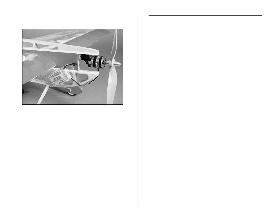
Note:The following image shows the installation of the
Park 450 motor with correct spacers between the motor
and mount.
Control Throws
1. Turn on the transmitter and receiver of your Edge 540
BP. Check the movement of the rudder using the transmitter.
When the stick is moved right, the rudder should also move
right. Reverse the direction of the servo at the transmitter if
necessary.
2. Check the movement of the elevator with the radio system.
Moving the elevator stick down will make the airplane
elevator move up.
3. Use a ruler to adjust the throw of the elevator, ailerons
and rudder. Adjust the position of the pushrod at the control
horn to achieve the following measurements when moving the
sticks to their endpoints.
Note: Measurements are taken at the widest point on
the surface.
Ailerons
Low Rate: 1-inch (25mm) with 20% Expo (Up/Down)
High Rate: 2-inch (50mm) with 40% Expo (Up/Down)
Elevator
Low Rate: 2-inch (50mm) with 20% Expo (Up/Down)
High Rate: 2
3
/
4
-inch (70mm) with 45% Expo (Up/Down)
Rudder
3
1
/
2
-inch (89mm) (Left/Right)
These are general guidelines measured from our own flight tests.
You can experiment with higher rates to match your preferred
style of flying.