Power system installation – E-flite Edge 540 BP 3D ARF User Manual
Page 24
4
E-flite Edge 540 BP ARF Assembly Manual
Power System Installation
Required Parts
Assembled airframe
Motor offset shim (2)
Stick mount w/hardware
Brushless motor
20-Amp Brushless ESC (EFLA311B)
910–1320mAh 3-Cell 11.1V Li-Po (THP13203SPL or THP9103SJPL)
Propeller
EC3 Device & Battery Connector, Male/Female (EFLAEC303)
Required Tools and Adhesives
Razor saw
Medium CA
Ruler
Hook and loop tape
Drill
Drill bit:
1
/
16
-inch (1.5mm)
Note: The following steps show the installation
procedures using our E-flite Outrunner BL motor. You can
use an Inrunner motor with a gearbox as an alternative
setup.
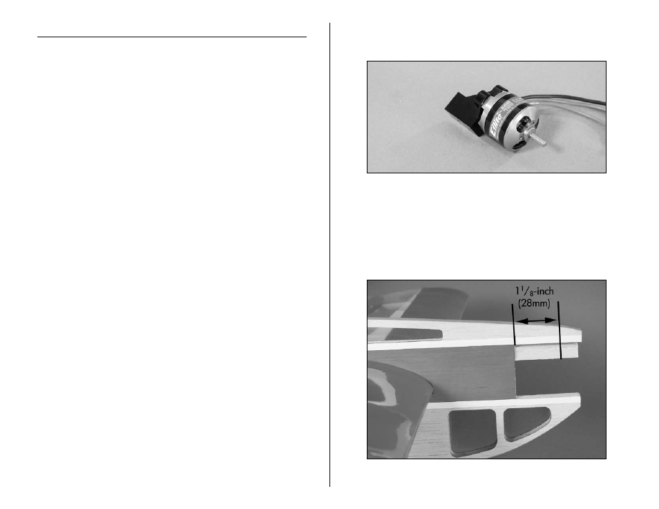
1. Mount your particular motor to the stick type mount using
the hardware provided with the mount.
Note: Use the included spacers when installing the
Park 450 motor.
2. Cut the Motor Stick to a length of
1
1
/
8
-inch (28mm) as
shown when using a Park 400 motor. When using a Park
450 motor, cut the motor stick to a length of
7
/
8
-inch (22mm).
- Habu 32x DF ARF (84 pages)
- A6M5 Zero 300 BNF Basic (17 pages)
- Hawker Sea Fury 480 ARF (28 pages)
- Mystique RES 2.9m ARF (52 pages)
- Super Cub 25e ARF (48 pages)
- AT-6 Texan 25 ARF (52 pages)
- LR-1A Pogo ARF 15e (21 pages)
- J-3 Cub 450 (40 pages)
- Hawker Hurricane 25e PNP (26 pages)
- Hawker Hurricane 25e PNP addendum (1 page)
- Apprentice 15e PNP (28 pages)
- Sukhoi SU-26m 480 ARF (28 pages)
- Beechcraft Bonanza 15e ARF (60 pages)
- Byp Yak 3D ARF (40 pages)
- Ultimate Fx 3D ARF (40 pages)
- Tribute FX 3D ARF (28 pages)
- Sobre 3D Profile (32 pages)
- Ascent EP Park Glider ARF (23 pages)
- Float Set Complete: Carbon-Z Cub (2 pages)
- Carbon-Z Cub PNP (27 pages)
- Carbon-Z Cub PNP Addendum (1 page)
- BAe Hawk 15 DF ARF (36 pages)
- Edge 540QQ 280 BNF Basic (19 pages)
- P-40 Warhawk 300 ARF (20 pages)
- Hawker Sea Fury 400 ARF (40 pages)
- Clipped Wing Cub 250 ARF (40 pages)
- T-34 Mentor 25e ARF (28 pages)
- Ultra Stick 25e ARF (40 pages)
- Ultra Stick 25e ARF Programming Guide (5 pages)
- Slick 3D 480 ARF (48 pages)
- PT-19 450 ARF (44 pages)
- Extra 330SC BP 3D ARF (40 pages)
- Cap 232 BP ARF (44 pages)
- Brio 10 ARF (56 pages)
- Park 480 BL Motor Combo (4 pages)
- Mini Edge 3D ARF (44 pages)
- Cessna 182 370 ARF (32 pages)
- Cessna 182/Park 400 BL Motor Combo (4 pages)
- Tribute 3D Profile ARF (40 pages)
- Fokker DVII 250 ARF (28 pages)
- Enticement F3P ARF (36 pages)
- Carbon-Z Yak 54 3X BNF Basic (23 pages)
- Carbon-Z Scimitar PNP (28 pages)
- UMX B-17G Flying Fortress BNF (18 pages)
- UMX Sbach 342 3D BNF Basic (17 pages)