E-flite Pulse XT 25e ARF User Manual
Page 5
Landing Gear Assembly and Installation
Required parts:
Fuselage
Main landing gear (wheels installed)
Wheel pants
(2) 6-32 x 1/2" socket head bolts
(2) #6 steel washers
(4) #2 x 3/8” sheet metal screws
Required tools and adhesives:
7/64” balldriver
Thin CA
Dremel rotary tool w/ cutoff wheel
#0 Philips screwdriver
1/16 in (1.5mm) drill bit
Threadlock
Pin drill
Felt-tip pen
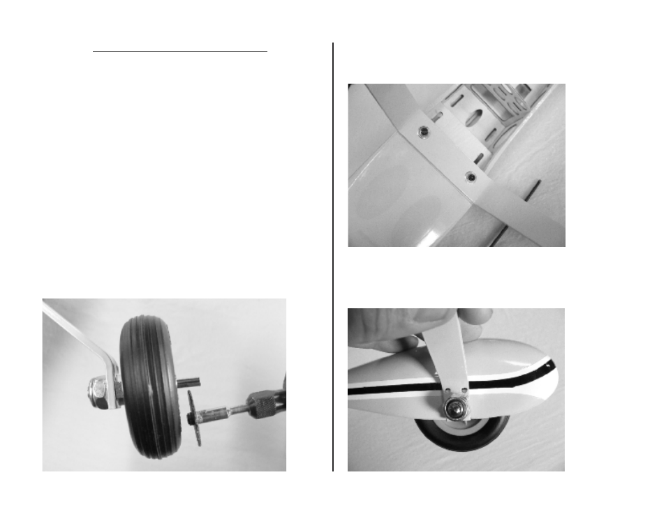
Ο Ο 1. The axles as supplied are suitable for the optional float kit installation
(EFLA500) and require trimming for use with wheel pants. Cut off the exposed
portion of the axle leaving approximately 1/4” protruding from the wheel
collar. Approximately 1” total axle length is the longest that will fit within the
wheel pant. A cutoff wheel in a rotary tool works well for this. Do this for both
main axles.
Ο 2. Use a 7/64” balldriver to install the landing gear on the fuselage with
two 6-32” x 1/2” socket head bolts and #6 steel washers. The landing gear
has a slight sweep and it should be installed on the model angled forward.
Threadlock may be used to prevent the bolts from loosening in flight.
Ο Ο 3. Locate the wheel pant on the landing gear and mark the hole locations
with a felt-tip pen. The trim lines on the wheel pant and fuselage can be used
to align the parts to each other. For another method see the E-tip on page 6.
5