Verify communications, Specifications – Banner SureCross DX80 Wireless Networks User Manual
Page 8
Verify Communications
After powering up and binding the Gateway and its Nodes, verify all devices are communicating properly. Verify LED 1 is green. Until
communication is established with the Gateway, the Node’s LED 2 flashes red. When communication is established, the Node’s LED 1
flashes green.
A Node will not sample its inputs until it is communicating with the Gateway to which it is bound.
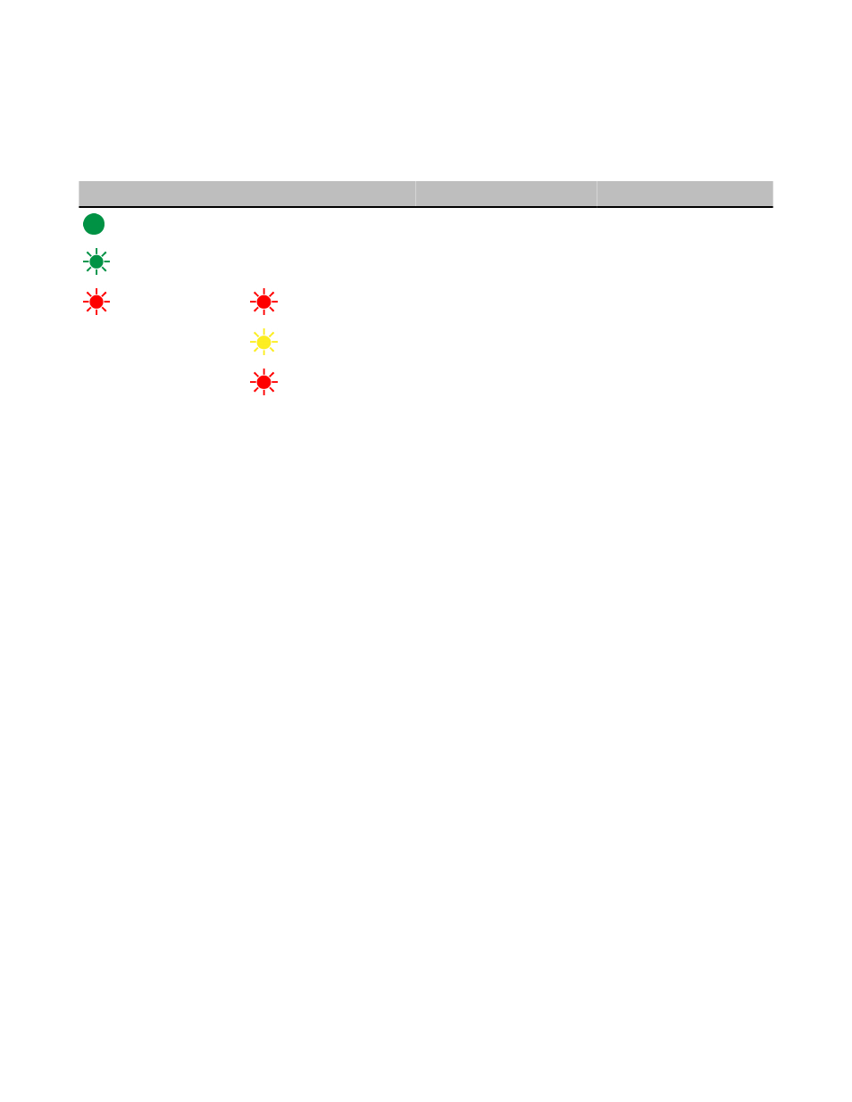
LED 1
LED 2
Gateway Status
Node Status
(green on)
Power ON
(green flashing)
RF Link OK
(red flashing)
(red flashing)
Device Error
Device Error
(yellow flashing)
Modbus Communication Active
(red flashing)
Modbus Communication Error
No radio link (when flashing
once every three seconds)
For Gateway and Ethernet Bridge systems, active Modbus communication refers to the communication between the Gateway and the
Ethernet Bridge. For GatewayPro systems, the Modbus communication LEDs refer to the communication internal to the Gateway Pro.
For Gateway only systems, the Modbus communication LEDs refer to the communication between the Gateway and its host system (if
applicable).
When testing the Gateway and Node, verify all radios and antennas are at least two meters apart or the communications may fail.
Specifications
Radio
Range
900 MHz: Up to 4.8 kilometers (3 miles) *
2.4 GHz: Up to 3.2 kilometers (2 miles) *
Transmit Power
900 MHz: 21 dBm conducted
2.4 GHz: 18 dBm conducted, less than or equal to 20
dBm EIRP
900 MHz Compliance (150 mW Radios)
FCC ID TGUDX80 - This device complies with FCC
Part 15, Subpart C, 15.247
IC: 7044A-DX8009
2.4 GHz Compliance
FCC ID UE300DX80-2400 - This device complies with
FCC Part 15, Subpart C, 15.247
ETSI/EN: In accordance with EN 300 328: V1.7.1
(2006-05)
IC: 7044A-DX8024
Spread Spectrum Technology
FHSS (Frequency Hopping Spread Spectrum)
Antenna Connection
Ext. Reverse Polarity SMA, 50 Ohms
Max Tightening Torque: 0.45 N·m (4 in·lbf)
Link Timeout
Gateway: Configurable
Node: Defined by Gateway
* With the standard 2 dB antenna. High-gain antennas are availa-
ble, but the range depends on the environment and line of sight.
To determine the range of your wireless network, perform a Site
Survey.
General
Power*
Requirements: +10 to 30V dc or 3.6 to 5.5V dc low
power option (For European applications: +10 to 24V
dc, ± 10% or 3.6 to 5.5V dc low power option)
Interface
Indicators: Two bi-color LEDs
Buttons: Two
Display: Six character LCD
SureCross DX80 FlexPower Solar Node
8
www.bannerengineering.com - tel: 763-544-3164
P/N 140373 rev. B