Wiring diagrams for analog inputs, Wiring diagrams for thermistor inputs, Wiring diagrams for discrete outputs – Banner SureCross DX80 Wireless Networks User Manual
Page 4: Additional information
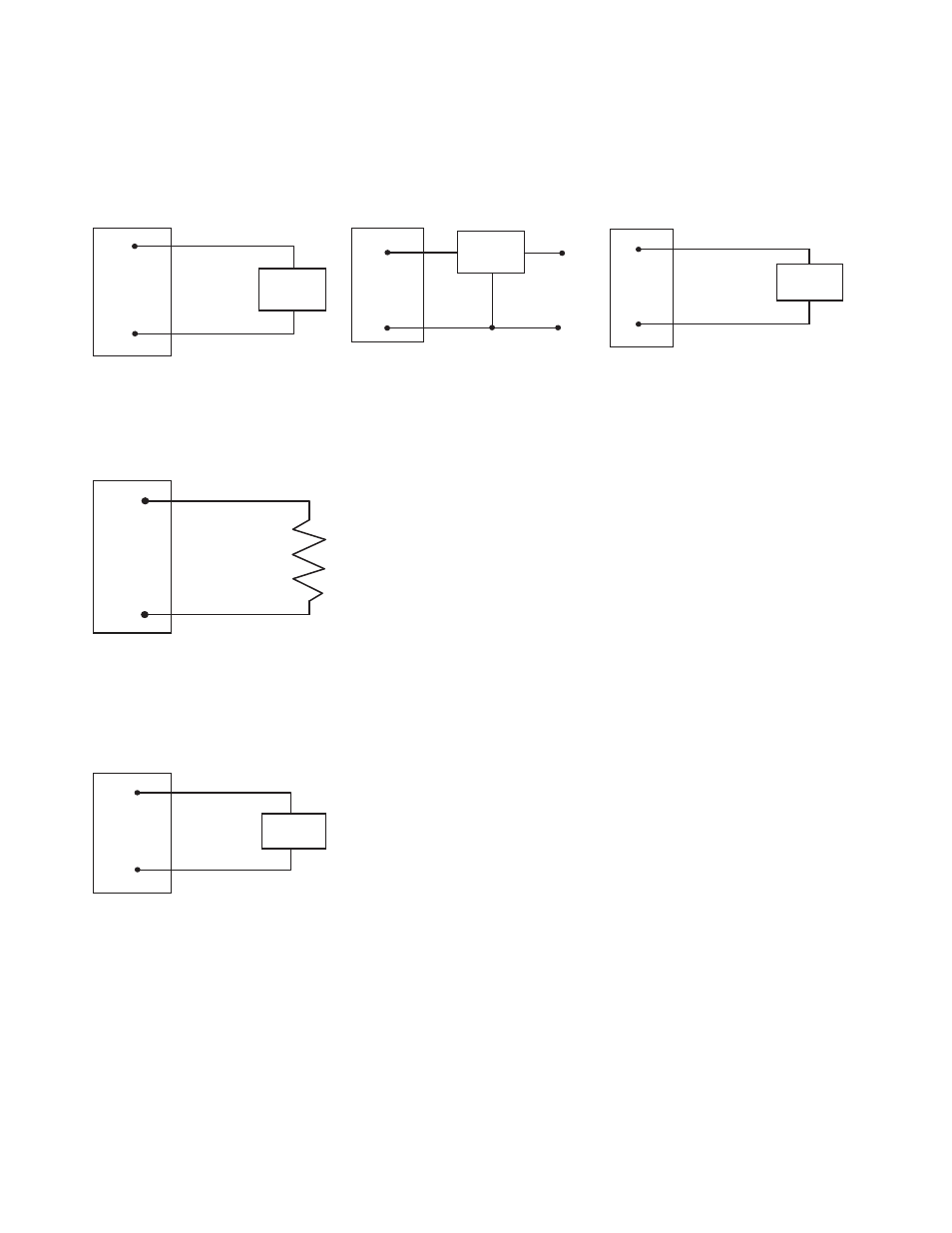
Wiring Diagrams for Analog Inputs
Connecting dc power to the communication pins will cause permanent damage. Do not exceed analog input ratings for analog inputs.
Only connect sensor outputs to analog inputs.
Analog Input Wiring (10 to 30V dc Pow-
er)
Analog Input Wiring (Externally Powered
Sensors)
Analog Input Wiring (Switch Powered
Sensors)
AIx
PWR
SureCross Device
SureCross Device
dc common
external
power
AIx or Ax+
GND
SureCross Device
AIx or Ax+
SPx
(Only possible in models with switch power
(SPx) outputs)
Wiring Diagrams for Thermistor Inputs
A4
GND
SureCross Device
Wiring Diagrams for Discrete Outputs
Connecting dc power to the communication pins will cause permanent damage. For the DX8x...C models, PWR in the wiring diagram
refers to V+ on the wiring board and GND in the wiring diagram refers to V- on the wiring board.
Discrete Output Wiring (NPN or NMOS)
DOx
PWR or SPx
SureCross Device
Additional Information
For additional information, including installation and setup, weatherproofing, device menu maps, troubleshooting, and a list of accesso-
ries, refer to one of the following product manuals
•
• SureCross Wireless I/O Network Manual:
• Web Configurator Manual (used with "Pro" and DX83 models):
SureCross DX80 FlexPower Solar Node
4
www.bannerengineering.com - tel: 763-544-3164
P/N 140373 rev. B