Use of auxiliary input (cl5 models) – Banner MAXI-AMP Series User Manual
Page 20
SM912
WHITE
BROWN
BLUE
NOTE: Black wire is not used
CL3
or
CL5
model
8
7
6
5
4
9
10
11
1
2
3
CL3
or
CL5
model
8
7
6
5
4
9
10
11
1
2
3
MAXI-BEAM
4
3
2
1
RPBT
PBT
1
2
3
4
MULTI-BEAM
CL3
or
CL5
model
8
7
6
5
4
9
10
11
1
2
3
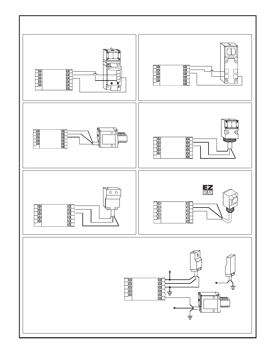
Sensor Hookup Diagrams for CL Series MAXI-AMP Modules
NOTE: the MAXI-AMP cannot power a MULTI-BEAM emitter and receiver pair.
Use a separate power source for the emitter (e.g.- power block PBA-1, etc.)
CL5 model MAXI-AMPs have an auxiliary input at terminal #9
which may be used for the interrogation or reset of the selected
logic function. This is accomplished by a switch closure between
pins #9 and #1 (Common). The auxiliary input may also be
switched by a DC device with an NPN transistor (current sinking)
output. The effect of the auxiliary input is described for each logic
function on page 6.
This example shows a typical inspection/rejection scheme which
uses a Banner MINI-BEAM as the inspection sensor. Typically,
the CL5 module would be programmed for the ONE-SHOT or
DELAYED ONE-SHOT logic function. If the SM312 "sees" an
acceptable condition when the SE612 senses the leading (or
trailing) edge of the product, the SM312 will inhibit a reject pulse
from occuring. Reject products will be ejected by the output pulse.
NOTE: the MAXI-AMP can supply 50mA for external 10 to 30V
dc devices. Carefully check the current draw of the devices to be
powered by the MAXI-AMP.
Use of Auxiliary Input (CL5 models)
NOTE: use power block model RPBT.
To MAXI-BEAM Sensors
To MINI-BEAM SM312 Series Sensors
To ECONO-BEAM SE612 Series Sensors
To MULTI-BEAM Sensors
To VALU-BEAM SM912 Series Sensors
NOTE: Black wire is not used
SM312
BROWN
BLUE
WHITE
CL3
or
CL5
model
8
7
6
5
4
9
10
11
1
2
3
NOTE: Black wire is not used
SE612
WHITE
BROWN
BLUE
CL3
or
CL5
model
8
7
6
5
4
9
10
11
1
2
3
+V dc @50ma
NOTE: Black wire is not used
+V dc
(#3)
NOTE: Black wire is not used
White
DATA
(Inspection)
GATE
(Interrogate)
Brown
SE61R
Inhibit
Blue
White
Brown
SM312
SE61E
Blue
(#1)
Brown
Blue
(#1)
+15V dc
(#3)
CL3
or
CL5
model
8
7
6
5
4
9
10
11
1
2
3
NOTE: use power block model PBT
or PBT2.
20
To EZ-BEAM Sensors
NOTE: White wire is not used
This hookup is for DC NPN (current
sinking) models of S18 Series,
Q25 Series, and other DC sensors
bearing the EZ-BEAM logo.
BROWN
BLUE
BLACK
CL3
or
CL5
model
8
7
6
5
4
9
10
11
1
2
3