Maxi-amp system, Hookup, Modules – Banner MAXI-AMP Series User Manual
Page 16: Maxi-amp, Models/dimensions, Beam pattern excess gain, Fiber optic mode, Glass fiber optics, With fof-400 fittings and fiber optics
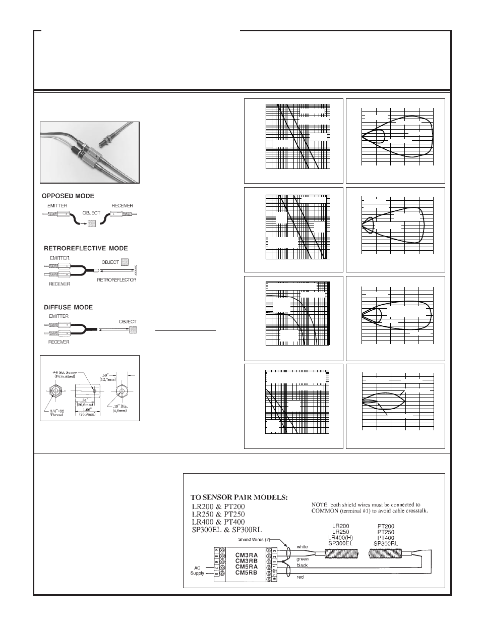
FIBER OPTIC Mode
glass fiber optics
Range: see excess gain curves
Temp. range: -40 to +100 degrees C
Fiber optic information:
IT13S: individual assembly
.06 in. (1,5mm) dia. bundle
IT23S: individual assembly
.12 in. (3mm) dia. bundle
BT13S:bifurcated assembly
.06 in. (1,5mm) dia. bundle
BT23S:bifurcated assembly
.12 in. (3mm) dia. bundle
L9: .5 in. (12mm) dia. lens
L16F: 1.0 in. (25mm) dia.
lens
Models/Dimensions
Sensors are epoxy-encapsulated and optics are hermetically sealed. Cables are 6 feet (2m) long. 30-foot (9m) cables available by special order.
Sensor accessories are shown on page 24.
FOF-400 Fiber optic Fitting
Hookup of LR/PT200, 250, 300, and 400
6
0
0
I
N
C
H
E
S
30
1
2
3
1
2
3
24
12
18
OPPOSED DISTANCE--INCHES
Opposed mode
w/IT13S fibers
w/IT23S fibers
LR/PT400
15
0
0
I
N
C
H
E
S
OPPOSED DISTANCE--FEET
30
45
75
8
16
24
8
16
24
60
Opposed mode
IT23S fibers and
L16F lenses
LR/PT400
IT23S fibers and
L9 lenses
5
0
0
I
N
C
H
E
S
25
3
6
9
3
6
9
20
10
15
w/L9 lens
w/L16F lens
DISTANCE TO REFLECTOR--FEET
Retroreflective mode,
with BRT-3 reflector and
BT13S fiber
LR/PT400
1
0
0
I
N
C
H
E
S
5
4
2
3
DISTANCE TO 90% WHITE TEST CARD--INCHES
Diffuse mode
w/BT13S fibers
w/BT23S fibers
0.2
0.4
0.6
0.6
0.4
0.2
LR/PT400
10
1
DISTANCE
100
1000
.1 IN
1 IN
10 IN
100 IN
Diffuse mode -- range based on
90% reflectance white
test card
with
BP13S
fibers
with
BT23S
fibers
E
X
C
E
S
S
G
A
I
N
I
LR/PT400
Beam Pattern
Excess Gain
10
1
DISTANCE
100
1000
.1 IN
1 IN
10 IN
100 IN
with IT23S
fibers
with IT13S
fibers
Opposed mode,
no lenses
E
X
C
E
S
S
G
A
I
N
I
LR/PT400
10
1
DISTANCE
100
1000
.1 FT
1 FT
10 FT
100 FT
Retroreflective mode, with
BT13S fibers
with L16F
lens
and BRT-3
reflector
with L9 lens
and BRT-3
reflector
E
X
C
E
S
S
G
A
I
N
I
LR/PT400
10
1
DISTANCE
100
1000
.1 FT
1 FT
10 FT
100 FT
Opposed mode,
with IT23S
fibers
with
L16F
lenses
with
L9
lenses
E
X
C
E
S
S
G
A
I
N
I
LR/PT400
MAXI-AMP System
Sensors for use with CM Series Modulated Amplifiers
16
LR400 & PT400
with FOF-400 fittings and
fiber optics
For complete information on glass
fiber optic assemblies and acces-
sories, see Banner product catalog.
Hookup
to CM Series
MAXI-AMP
Modules
The hookup diagrams on this page and the
next include all of the remote sensors for use
with CM Series modulated amplifier mod-
ules. It is important to note how the shield wire
of a remote sensor is wired. The shield wire is the
uninsulated wire in each sensor cable. Failure to
connect the shield as shown may result in false
operation of the amplifier. When wiring emit-
ters, it is good practice to connect the positive
(white) wire first. LEDs are sensitive to applica-
tion of the wrong voltage, and can easily be
destroyed.
NOTE: up to three sensors may be connected to
each amplifier (see specifications).
The threaded barrel design of the
LR400 and PT400 (see page 14) per-
mit the connection of any Banner
glass fiber optic assembly by using
two model FOF-400 fittings. The
sensors are typically mounted
through 3/8 inch (10mm) diameter
clearance holes, with the FOF-400
fittings threaded onto them after
mounting. Setscrews in the fittings
lock the fibers in place, but allow
rapid replacement without disturb-
ing any electrical wiring.
As the excess gain curves show, the
LR/PT400 combination produces a
high-performance fiber optic sens-
ing system. With the amplifier's 1
millisecond response time, this sys-
tem can be used for almost any fiber-
optic requirement.