Timing logic programming (cm5 and cr5 models), Amplifier programming (all models) – Banner MAXI-AMP Series User Manual
Page 12
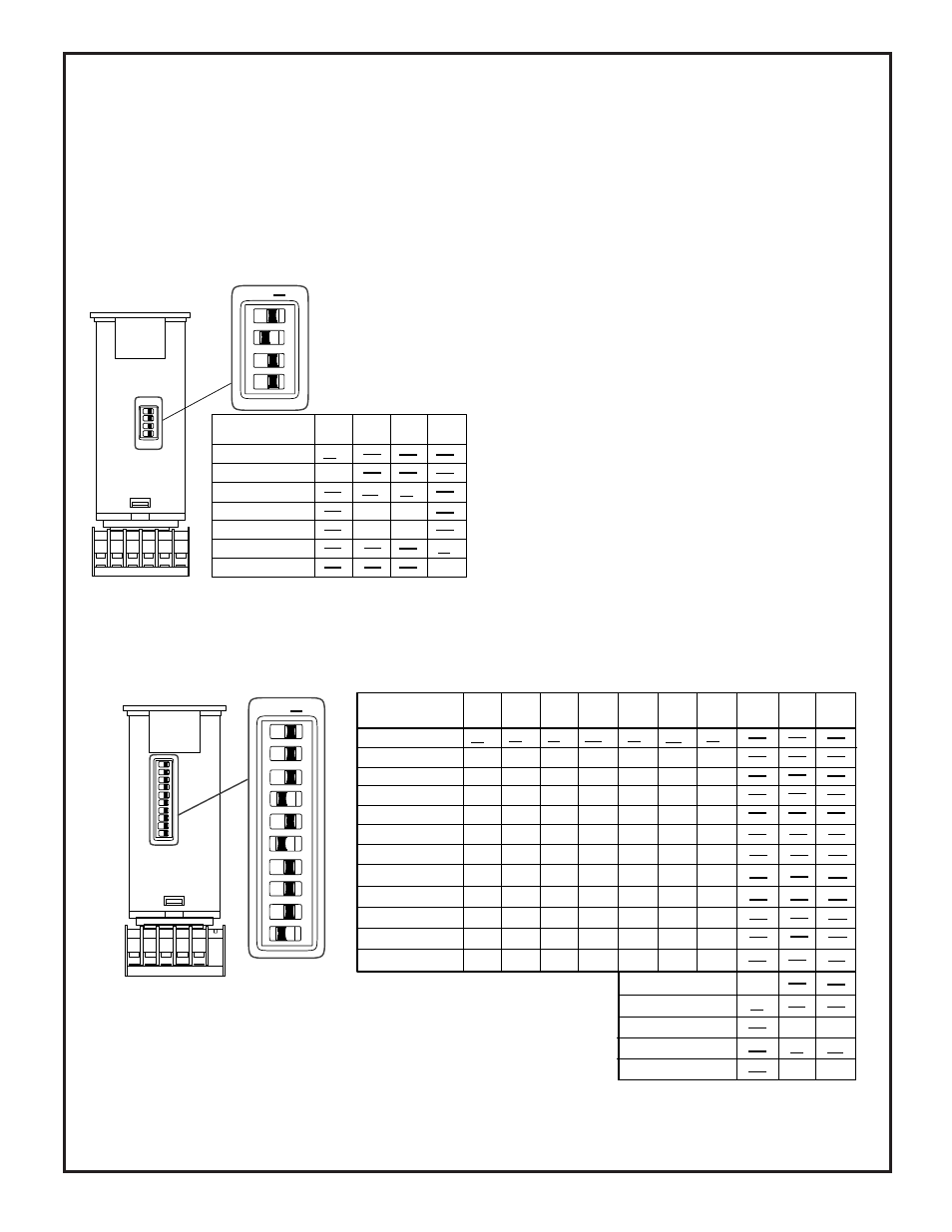
Settings illustrated below are factory settings. Factory settings are "underlined" in the table.
Factory settings shown at
left. "Underlined" settings
in table below are factory
settings.
Timing Logic Programming (CM5 and CR5 models)
The diagram shows switch locations, and the
table summarizes the program switch
positions.
A group of ten switches, located on the side of the module opposite the amplifier program
switches, is used to select the timing logic for the CM5 and CR5 models.
Switches #1 through #7 are used to select the logic function. Switch #8 programs the output
for either NORMALLY OPEN or NORMALLY CLOSED operation. Switches #9 and #10
program the time range(s). There are three ranges: 10 to 150 milliseconds, 0.1 to 1.5 seconds,
and 1 to 15 seconds. The programmed range will be the same for both functions of a dual
timing mode (ON & OFF DELAY, DELAYED ONE-SHOT, and REPEAT CYCLE).
However, DELAY and HOLD times are independently adjustable within the selected range.
12
The diagram at the left shows the location of switches 1-4,
and the table summarizes the settings required for each
response condition.
NOTE: an adhesive-backed mylar label is supplied, which
may be marked to indicate switch programming and then
applied to the MAXI-AMP housing as a switch cover.
Amplifier response conditions may be programmed via the group of four
switches located on one of the narrow sides of the MAXI-AMP module.
Switch #1 selects the amount of amplifier hysteresis. Hysteresis is the
amount of signal change beyond the switching threshold which is
required to cause the amplifier output to change state, and is expressed
as a percent of amplifier gain. The NORMAL setting of 20% should
always be used, except for low contrast situations such as many color
registration applications.
NOTE: the LOW hysteresis setting should be used only when all
sensing conditions remain stable. "Buzzing" of the output (in ON/
OFF and LIMIT operation) or false outputs (in DELAY, ONE-
SHOT, or LATCH operation) may occur if sensing variables (e.g.-
web flutter) result in optical contrast approaching unity.
Switches #2 and #3 are used to program the amplifier response time.
The 10 millisecond setting should be used whenever possible for the
greatest immunity to electrical interference ("noise"). The 2 millisec-
ond setting has more interference rejection than the 0.3 millisecond
mode. Sensor performance (excess gain) is identical in all three
response settings.
Amplifier Programming (all models)
Switch #4 is used to select LIGHT OPERATE or DARK
OPERATE. In the LIGHT OPERATE mode, the output will
energize (in ON/OFF or LATCH operation) or the timing
function will initiate (in DELAY, ONE-SHOT, or LIMIT
operation) when the receiver "sees" sufficient light (excess
gain greater than 1X). In DARK OPERATE, the output will
energize or timing will begin when the receiver is suffi-
ciently dark (excess gain less than 1X).
ON
ON
ON
OFF
AMPLIFIER
PROGRAMMING
#1
#2
#3
#4
SWITCH
SWITCH
SWITCH
SWITCH
ON
O
F
F
1
2
3
4
Normal hysteresis (20%)
Low hysteresis (5%)
10 millisecond response
2 millisecond response
0.3 millisecond response
Light operate
Dark operate
ON
ON
ON
OFF
OFF
OFF
ON
OFF
ON
ON
ON
ON
OFF
ON
OFF
ON
PROGRAMMING
TIMING LOGIC
#1
#2
#3
#4
#5
#6
#7
#8
#9
#10
10
ON
O
F
F
1
2
3
4
5
6
7
8
9
SWITCH
SWITCH
SWITCH
SWITCH
ON
ON
ON
ON
OFF
OFF
OFF
SWITCH
SWITCH
SWITCH
SWITCH
SWITCH
SWITCH
On/Off
On Delay
Off Delay
On and Off Delay
One-shot
Delayed One-shot
Limit
Repeat Cycle
AC Latch
DC Latch
Delay and Latch
Limit and Latch
ON
ON
OFF
ON
OFF
ON
OFF
OFF
OFF
OFF
ON
ON
OFF
OFF
OFF
ON
OFF
ON
OFF
OFF
OFF
OFF
OFF
ON
ON
ON
OFF
OFF
OFF
OFF
OFF
ON
ON
OFF
ON
OFF
ON
ON
OFF
ON
ON
ON
ON
ON
ON
OFF
ON
ON
ON
ON
ON
OFF
OFF
ON
ON
ON
ON
ON
OFF
OFF
OFF
ON
ON
N/C Output
N/O Output
.15 Sec. Max. Time
1.5 Sec. Max. Time
15 Sec. Max. Time
OFF
OFF
OFF
OFF
ON
ON
OFF
ON
OFF
ON
OFF
ON