Maxi-amp cm and cr series specifications, Dimension drawing, Functional schematics – Banner MAXI-AMP Series User Manual
Page 11: Generalized hookup
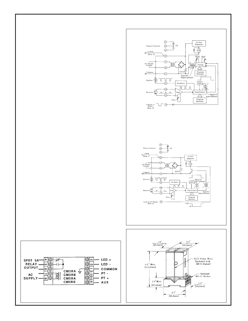
Dimension Drawing
NOTE #1: power is available at pins #3 (+) and #1 (-) for an external 10 to 30V dc
device (see hookup example, page 17). Current available is 40 mA at 120V ac (240V
ac) line level; 30mA at 105V ac (210V ac) line level. Alternately, the module may
be powered by 12 to 28V dc at pins #3 (+) and #1 (-). Do not connect ac voltage if using
external dc power.
NOTE #2: pulling pin #9 low (to common) will inhibit the timing, or reset the latch
of CM5 or CR5 models (see "Description of Logic Functions", page 6).
CM5 & CR5 Models
Functional Schematics
CM3 & CR3 Models
NOTE #3: pin #9 of CM3 or CR3 models may be connected directly to the
AUXILIARY input of a MAXI-AMP or Banner M Series module. It may also serve
as the input to Banner CL series MAXI-AMPs or to Banner Plug Logic modules (see
hookup example, page 17).
11
SUPPLY VOLTAGE:
Models CM3(R)A, CM5(R)A, CR3(R)A, and
CR5(R)A: 105 to 130V ac, 50/60Hz (4 VA), or 12 to 28V dc* at 70mA.
Models CM3(R)B, CM5(R)B, CR3(R)B, and CR5(R)B: 210 to 250V ac, 50/
60Hz (4 VA), or 12 to 28V dc* at 70mA.
*NOTE: do not connect ac power if using external dc power.
OUTPUT CONFIGURATION:
Models CM3A, CM3B, CM5A, CM5B, CR3A, CR3B, CR5A, CR5B have
SPST solid-state relay for switching ac or dc (see page 10).
Models CM3RA, CM3RB, CM5RA, CM5RB, CR3RA, CR3RB, CR5RA,
CR5RB have SPDT electromechanical (e/m) relay with the following ratings:
CONTACT RATING: 250V ac max, 24V dc max, 5 amps max. (resistive load),
1/10 H.P. at 240V ac. Install transient suppressor (MOV) across contacts which
switch inductive loads.
CONTACT RESPONSE: 10 milliseconds max. open/close;
20 operations/second max.
MECHANICAL LIFE: 20,000,000 operations
CM3 and CR3 models also have a logic level current sinking NPN transistor
switch at pin #9. See schematic (right) and hookup info.
AMPLIFIER:
RESPONSE SPEED: programmable for 10, 2, or 0.3 milliseconds. NOTE: use
10 millisecond setting whenever possible for enhanced noise rejection.
HYSTERESIS: if programmed "HIGH", approximately 20%; if programmed
"LOW", approximately 5%. NOTE: see cautions for "LOW" setting, page 12.
MODULATION FREQUENCY: approximately 10kHz.
SENSOR LEAD LENGTH:
50 feet (15 m) maximum. Use separate
shielded cable for emitter and receiver, or order sensors with extended cable
length. NOTE: see splicing precautions, page 17.
MULTIPLE SENSOR HOOKUP:
Up to three sensors may be wired
together to one CM-series amplifier for "OR" operation (in LIGHT operate) or
"NAND" operation (in DARK operate). Emitters are connected in series, and
receivers are connected in parallel. When wiring two sensors to one MAXI-
AMP, multiply excess gain data for each sensor by 1/2 (obtain data from
applicable excess gain curve). When wiring three sensors to one MAXI-AMP,
multiply excess gain by 1/3.
TIMERS (CM5 models only):
TIMING RANGES: LOW range - 10 to 150 milliseconds
MIDDLE range - 0.1 to 1.5 seconds
HIGH range - 1 to 15 seconds
REPEATABILITY: +/-2% of set time over all extremes of supply
voltage and temperature
ADJUSTMENTS:
Miniature switches for programming of LIGHT/ DARK
operate, amplifier response time, amplifier hysteresis, normally open or nor-
mally closed output, and timing function (CM5 & CR5 models). 15-turn
clutched potentiometer for gain and time setting(s) (CM5 and CR5 models).
OPERATING TEMPERATURE:
0 to 50
°
C (32 to 122
°
F).
INDICATOR LEDs:
Red indicator LED is "ON" when the module output
is energized. Exclusive Banner Alignment Indicating Device (AID™) system
lights a red LED indicator whenever the receiver "sees" its own modulated light
source, and pulses it at a rate which is proportional to the strength of the received
light signal.
CONSTRUCTION:
Rugged NORYL
®
polyphenylene oxide (PPO
®
) hous-
ing, 1.6" x 2.3" x 4". Standard round-pin 11-pole plug base.
NOTE: If MAXI-AMP is powered by a dc power supply, connect +12 to 28V dc
@
≥
70mA to terminal #3 and dc common to terminal #1.
Make no connections to terminal #7 or #8.
Generalized Hookup
models with electromechanical relay output
MAXI-AMP CM and CR Series Specifications