Specifications, Performance curves – Banner U-GAGE T30U—Level Control User Manual
Page 5
Specifications
Proximity Mode Range
“A” suffix models: 150 mm (5.9 in) min. near limit; 1 m (39 in) max. far
limit
“B” suffix models: 300 mm (11.8 in) min. near limit; 2 m (79 in) max.
far limit
Supply Voltage
12 to 24V dc (10% max. ripple) at 90 mA, exclusive of load
Supply Protection Circuitry
Protected against reverse polarity and transient voltages
Output Configurations
SPST solid-state switch; choose NPN (current sinking) or PNP (current
sourcing) models
Output Ratings
Dual Discrete Outputs: 100 mA maximum, total – both outputs
OFF-state leakage current: less than 10 microamps
ON-state saturation voltage: less than 1V at 10 mA and less than
1.5V at 100 mA
Output Protection
Protected against continuous overload and short-circuit; transient over-
voltage; no false pulse on power-up
Output Response Time
“A” suffix models: 48 milliseconds
“B” suffix models: 96 milliseconds
Sensing Performance
Sensing repeatability: ±0.25% of distance
Minimum window size: 10 mm (0.4 in)
Hysteresis of discrete output: 2.5 mm (0.10 in)
Adjustments
Sensing window limits: TEACH-mode programming of near and far
window limits may be set using membrane push buttons on sensor or
remotely via TEACH input. Window limits may be programmed separate-
ly, or together
Construction
Molded reinforced thermoplastic polyester housing
Environmental Rating
Leakproof design is rated IEC IP67, NEMA 6P
Connections
2 m (6.5 ft) or 9 m (30 ft) 5-conductor PVC-covered attached cable, or 5-
pin Euro-style quick-disconnect fitting
Operating Conditions
Temperature: −20° to +70° C (−4° to +158° F)
Humidity: 100% maximum relative humidity
Vibration and Mechanical Shock
All models meet Mil. Std. 202F requirements. Method 201A (Vibration:
10 to 60Hz max., double amplitude 0.06 in, maximum acceleration 10G).
Also meets IEC 947-5-2 requirements: 30G, 11 ms duration, half sine
wave
Certifications
Application Notes
Objects passing inside the specified near limit will produce a false re-
sponse
Indicators
Status LEDs:
Run Mode
Program mode
Green
ON – Power ON, Run mode
Flashing – Output is overloaded
OFF – Program Mode
Red
Flashing – Relative received signal strength
Flashing – Relative received signal strength
Yellow (2)
ON – Output energized (conducting)
ON – Ready for first window limit
Flashing – Ready for second limit
OFF – Not teaching this output
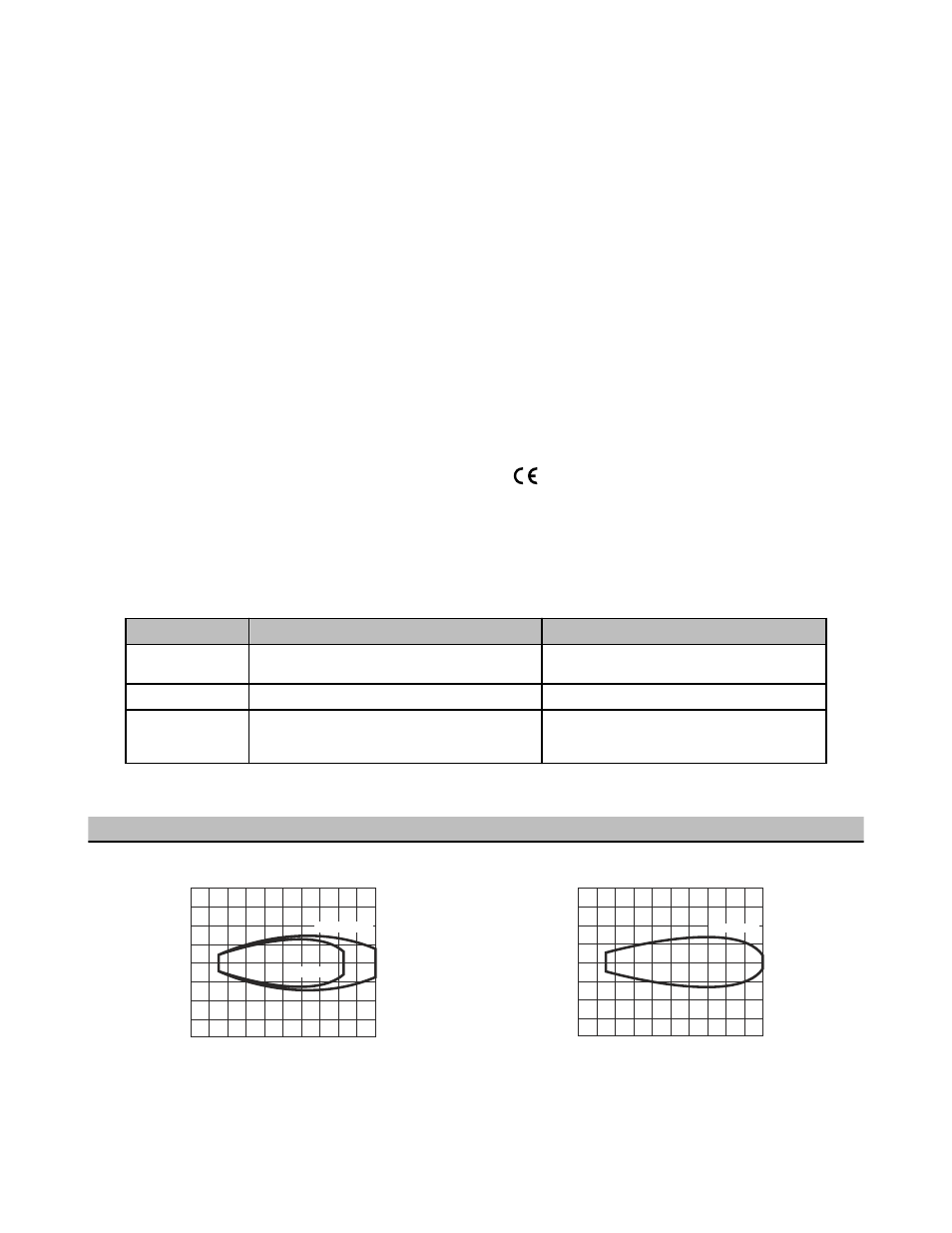
Performance Curves
with Plate Target (Typical)
0
0
200 mm
(8.0 in)
400 mm
(16.0 in)
600 mm
(24.0 in)
800 mm
(32.0 in)
1000 mm
(40.0 in)
50
50
100
100
150
150
200
200
0
2.0 in
2.0 in
4.0 in
4.0 in
6.0 in
6.0 in
8.0 in
8.0 in
DISTANCE
100 x 100 mm
10 x 10 mm
WIDTH
(mm)
Figure 7. 1-Meter Models
0
0
400 mm
(16.0 in)
800 mm
(32.0 in)
1200 mm
(48.0 in)
1600 mm
(64.0 in)
2000 mm
(80.0 in)
100
100
200
200
300
300
400
400
0
4.0 in
4.0 in
8.0 in
8.0 in
12.0 in
12.0 in
16.0 in
16.0 in
100 x 100 mm
DISTANCE
WIDTH
(mm)
Figure 8. 2-Meter Models
U-GAGE® T30 Series with Dual Discrete Outputs
P/N 059200 Rev. E
www.bannerengineering.com - tel: 763-544-3164
5