Sensor programming – Banner U-GAGE T30U—Level Control User Manual
Page 2
Sensor Programming
Window limits may be taught to the sensor in several ways. The following methods describe the programming procedures using the push buttons on the back of the sensor;
remote programming (remote TEACH) procedures are described in
NOTE: When the sensor changes state between Program and Run modes, all of the LED indicators turn OFF momentarily, before the
appropriate LEDs turn ON as described below. The sensing window limits expand temporarily to full scale (max range) during Program
mode.
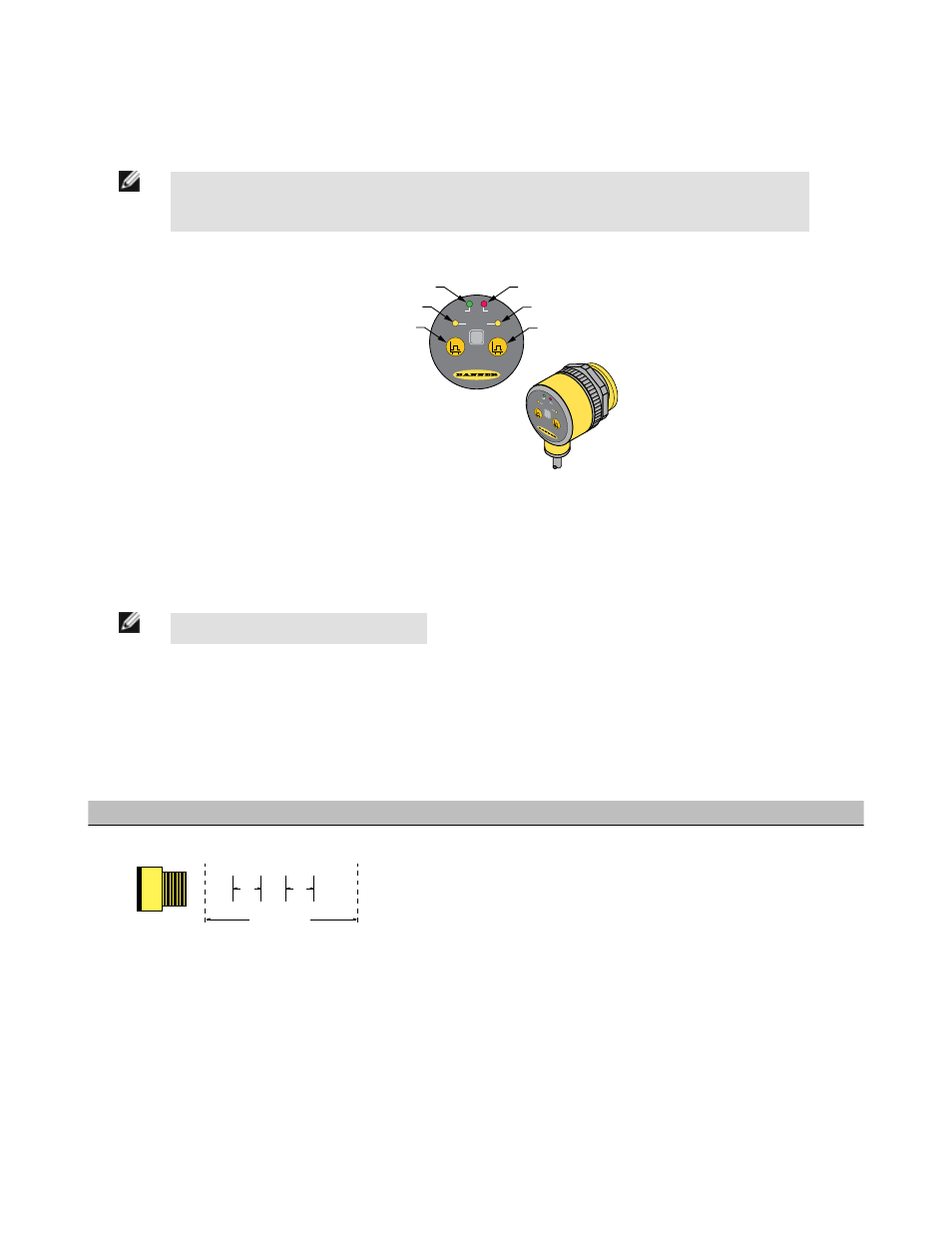
Green Power ON/OFF LED
Yellow Output 1 LED
Red Signal Strength LED
Output 1
Programming Push Button
Yellow Output 2 LED
Output 2
Programming Push Button
U-GAGE
™
WHITE
1
2
POWER
SIGNAL
OUTPUT
DUAL
DISCRETE
BLACK
U-GAGE
™
WHITE
1
2
POWER
SIGNAL
OUTPUT
DUAL
DISCRETE
BLACK
Figure 1. U-GAGE T30 Series sensor programming push buttons and indicators
Program the outputs independently to define separate sensing windows (both their size and placement) or program the outputs simultaneously for complementary or fixed
field operation.
Sensing windows may be as large as 0.85 m for 1 m range models, and as large as 1.7 m for 2 m range models. Use the procedures as described, or combine them for
specialized applications.
NOTE: Output 1 = White wire, Output 2 = Black wire
General Notes on Programming:
1. The sensor returns to Run mode if the first TEACH condition is not registered within 120 seconds.
2. After the first limit is taught, the sensor remains in Program mode until the TEACH sequence is finished.
3. Press and hold the programming push button > 2 seconds (before teaching the second limit) to exit Program mode without saving any changes. The sensor will
revert to the last saved program.
4. The sensor allows for some forgiveness in the teaching of a set point. If both near and far limits are not exactly the same (but are closer than the minimum 10 mm
required to define a window), the sensor will set a 10 mm window with the center at the “average” of the two limits.
To Program Separate Sensing Window Limits
1
Sensing Range
2
Output
Output
Separate Sensing Window Limits
Dead Zone
Figure 2. Programming separate sensing window limits
Each output conducts when the target is inside that output’s window limits. The two sets of window
limits may overlap or be completely independent.
1. Press and hold the push button for the selected output until the green Power LED turns
OFF and the yellow LED for the programmed output turns ON.
2. Position the target at the first limit and click the push button. The yellow Output LED flash-
es.
3. Position the target at the second limit and click the push button. The green Power LED
turns ON. The sensor is in Run mode.
4. Repeat the procedure for the second output, if desired.
U-GAGE® T30 Series with Dual Discrete Outputs
2
www.bannerengineering.com - tel: 763-544-3164
P/N 059200 Rev. E