Machine safety switches, Si-ls31h series, Overview – Banner SI-HG63 Hinge Style Switches User Manual
Page 4: Mechanical installation, Electrical installation
Machine Safety Switches –
SI-LS31H Series
P/N 50165 rev. D
Banner Engineering Corp. • Minneapolis, MN U.S.A.
www.bannerengineering.com • Tel: 763.544.3164
Overview
Series SI-LS31H safety interlock switches have a built-in hinged lever actuator that
mounts to a hinged door or flap to detect its being opened. The actuator head may be
rotated on the interlock body in any of four positions (see Figure 1).
Mechanical Installation
1. With actuator in the normal position, loosen the four screws holding the actuator head
to the switch body and carefully rotate the actuator head to the desired position (see
Figure 1). Re-tighten the four screws.
2. User tamper-resistant hardware, such as one-way screws, to attach lever actuator and
to mount the switch body.
3. If possible, align lever pivot point with the axis of the door or flap.
IMPORTANT: A safety switch must be installed in a manner which discourages
tampering or defeat. Mount each switch to prevent bypassing of the switching
function at the terminal chamber. Overtravel may cause damage to switch.
Model SI-LS31HGD is used on doors or flaps which open a maximum of 90° in either
direction, beginning with the lever in a vertical position (see Figure 2, top).
Models SI-LS31HGRD and SI-LS31HGLD are used on doors and flaps which open in
one direction, beginning with the lever in a horizontal position (see Figure 2, bottom).
Electrical Installation
Access to the Wiring Chamber
The wiring chamber is accessed via a hinged cover door which may be pried open using
a flat-blade screwdriver (see the dimension drawings on page 7). A conduit adapter is
supplied to convert the German M20 x 1.5 thread to ½" x 14 NPT. An accessory cable
gland which fits the M20 x 1.5 thread is available (see page 7).
Connection to a Machine
Two types of contacts are offered. The contacts between terminals 11–12 and 21–22
are the safety contacts, which are closed (i.e., they conduct) when the actuator is in
the home (0°) position. The contacts located between terminals 23–24 are considered
monitoring contacts, which should not be used for safety switching.
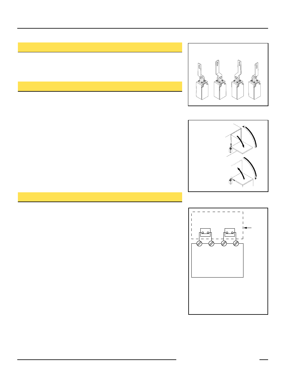
As illustrated in Figure 3, a normally-closed safety contact (i.e., a safety contact that is
closed when the actuator is in the home [0°] position) from each of two safety switches
per interlock guard must connect to a 2-channel safety module or safety interface in
order to achieve a control reliable interface to the master stop control elements of a
machine. Examples of appropriate safety modules include 2-channel emergency stop
(E-stop) safety modules and gate monitor safety modules.
Two functions of the safety module or safety interface are:
1. to provide a means of monitoring the contacts of both safety switches for contact
failure, and to prevent the machine from restarting if either switch fails; and
2. to provide a reset routine after closing the guard and returning the safety switch
contacts to their closed position. This prevents the controlled machinery from restarting
by simply moving the safety switch actuators. This necessary reset function is required
by ANSI B11 and NFPA 79 machine safety standards.
Actuator head may be rotated
in 90° increments.
Figure 1. Features
Figure . Door opens in one direction
Safety
Switch
#1
Safety
Switch
#2
Input
Channel
#1
Input
Channel
#2
2-channel Safety Module
(2-channel E-stop Module
2-channel Gate Monitor Module, etc.)
Single gate
or guard
11 12
11 12
NOTE: Refer to the installation
instructions provided with the
safety module for information
regarding the interface of the
safety module to the machine stop
control elements.
Figure 3. Connect two redundant safety
switches per interlock guard to an
appropriate -channel input safety
module.
Model
SI-LS31HGD
Models
SI-LS31HGRD
SI-LS31HGLD