Machine safety switches, Si-ls31h series, Models – Banner SI-HG63 Hinge Style Switches User Manual
Page 3: Model actuator contact configuration, Contact configuration, Switching diagram
Machine Safety Switches –
SI-LS31H Series
P/N 50165 rev. D
3
Banner Engineering Corp. • Minneapolis, MN U.S.A.
www.bannerengineering.com • Tel: 763.544.3164
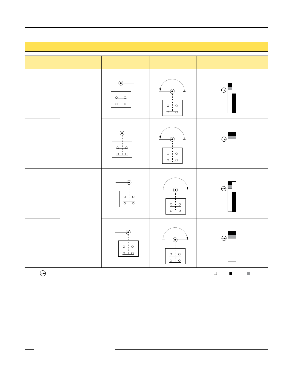
Model
Actuator
Contact Configuration
(Lever in Normal Position)
Contact Configuration
(Lever Rotated)
Switching Diagram
SI-LS31HGRD
Right-hand
Hinged Lever 180°
SI-LS31HGRE
SI-LS31HGLD
Left-hand
Hinged Lever 180°
SI-LS31HGLE
Models
23
24
11
12
0°
23
24
11
12
0°
23
24
11
12
180°
0°
23
24
11
12
180°
0°
8°
5°
0°
10°
180°
11-12
23-24
Safety
Monitor
8°
5°
0°
10°
180°
11-12
23-24
Safety
Monitor
21
22
11
12
0°
21
22
11
12
180°
0°
8°
5°
0°
180°
11-12
21-22
Safety
Safety
21
22
11
12
0°
21
22
11
12
180°
0°
Contacts: Open Closed Transition
NOTE:
This symbol for a positive opening safety contact (IEC 60947-5-1) is used in the
switching diagrams to identify the point in actuator travel where the normally closed
safety contact is fully open.
8°
5°
0°
180°
11-12
21-22
Safety
Safety