Model ppe-g/ppe-p enclosure kit, Installation, Remove enclosure housing from base – Banner PPE-P PresencePLUS Pro Enclosures User Manual
Page 2: Install the presenceplus pro camera, For applications with vibration
Model PPE-G/PPE-P Enclosure Kit
2
P/N 115342 rev. A
Banner Engineering Corp.
•
Minneapolis, MN U.S.A.
www.bannerengineering.com • Tel: 763.544.3164
Model PPE-G/PPE-P Enclosure Kit
P/N 115342 rev. A
3
Banner Engineering Corp.
•
Minneapolis, MN U.S.A.
www.bannerengineering.com • Tel: 763.544.3164
Installation
Remove Enclosure Housing from Base
NOTE: It is not necessary to remove the end cap and window to install the camera.
1. Remove five screws from around base of housing using a #2 Phillips head
screwdriver.
2. Lift back of housing up off the base, slide housing forward until it clears the front
end cap, and separate the housing from the base.
Install the PresencePLUS Pro Camera
1. Verify that the lens is mounted on the camera.
2. Check the fit of the camera/lens assembly. The lens should be positioned about
flush with the base’s front edge. When using lenses of greater than 25 mm focal
length, remove the camera bracket and mount it in reverse position so the camera
can be moved further back.
3. Mount the camera on the camera bracket, using the four supplied M3x6 socket head
screws, lock washers and flat washers. Tighten the camera screws with the included
2.5 mm hex wrench.
4. Slide the camera and bracket so the front of the lens is approximately flush with the
front of the base, and tighten the two bracket screws on the bottom of the base.
Mounting the Enclosure Base – Without the Optional Mounting Bracket
1. Drill four holes for #8 screws into the mounting surface. Use the base as a template
or see the dimension drawing on page 4. (Mounting holes may be clearance drilled
or tapped.)
2. Mount the base using four #8 screws of sufficient length (user-supplied).
Mounting the Enclosure Base – Using the Optional Mounting Bracket
1. Assemble the bracket to the enclosure base (to either side of the enclosure), using
the hardware supplied with the bracket.
2. Drill two holes for 1⁄4" screws into the mounting surface. Use the bracket as a
template. (Mounting holes may be drilled or tapped.)
3. Mount the base using two 1⁄4" screws of sufficient length (user-supplied).
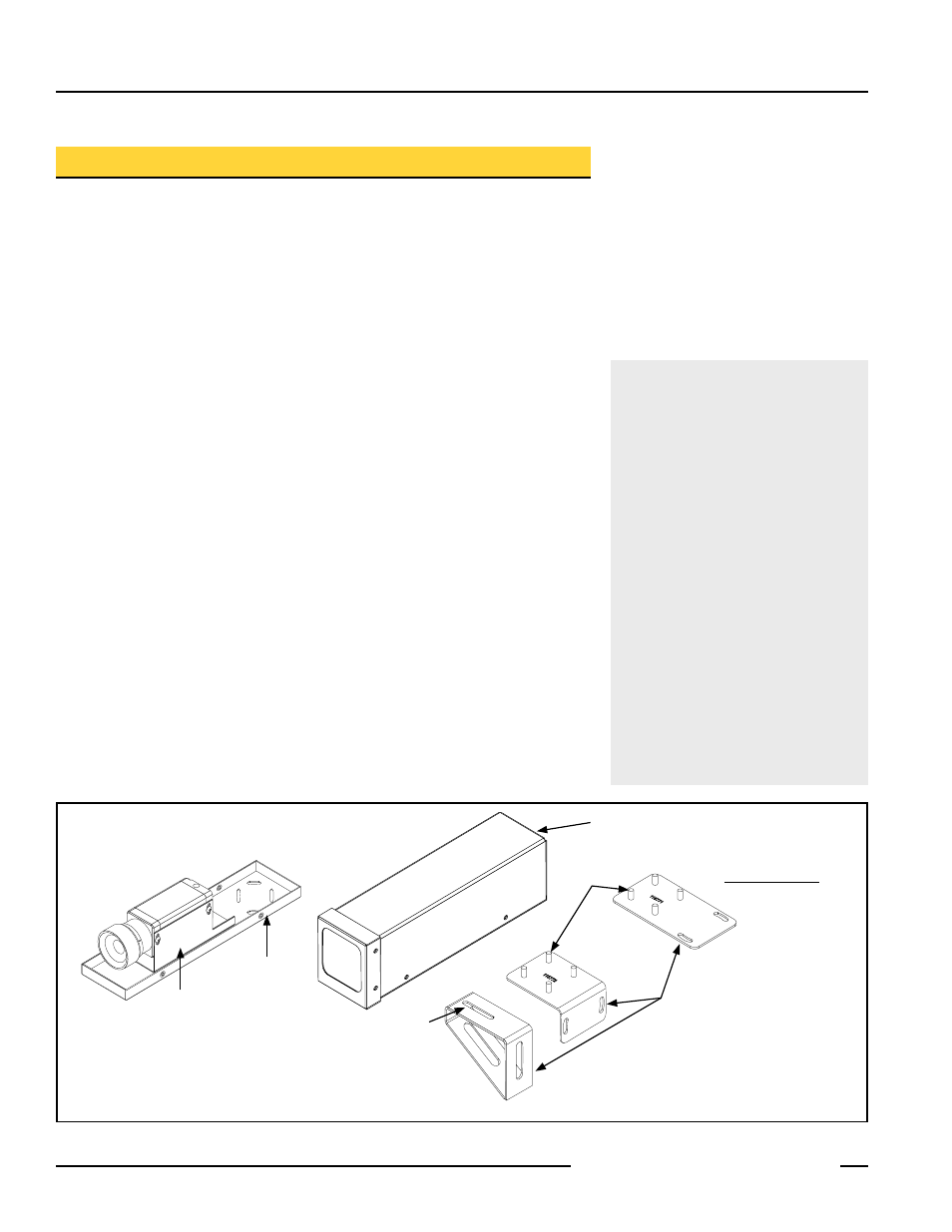
Figure 1. Assembling the enclosure
Enclosure Base
Camera Bracket
Enclosure Housing
Model SMBPPES
Flat Bracket
Model SMBPPEA
Right-Angle Bracket
Optional Enclosure
Mounting Brackets
For Applications with Vibration
If the Right-Angle Bracket is to be used
to mount the enclosure in a vibration
application, the optional Front Bracket
(SMBPPEF) is required. Use it to stabilize
the front of the enclosure after it is
mounted, aimed, and assembled.
1. The Front Bracket fastens to the PEM nut
on the bottom of the enclosure, using the
#10 screw and washers supplied with the
bracket. Remove the clear dust seal over
the PEM nut first.
2. To mount the side of the bracket to the
mounting surface, use the bracket as a
template to mark the hole location. Drill
a hole for a 1⁄4" screw in the mounting
surface.
3. The slots in the Front Bracket allow some
additional adjustment after mounting, if
needed.
Model SMBPPEF
Front Bracket for Vibration Applications
Clearance for 1⁄4" screws
washers and nuts
included
screw and washer
included