Device configuration – Banner SureCross DX80 Wireless Networks User Manual
Page 6
I/O
Poin
t
Modbus Holding Register
I/O Type
Units
I/O Range
Holding Register
Representation
Terminal
Block La-
bels
Gateway
Any Node
Min.
Value
Max.
Value
Min.
(Dec.)
Max.
(Dec.)
13
13
13 + (Node# × 16)
Link Loss, ND 1
-
0
1
0
65535
DO5
14
14
14 + (Node# × 16)
Link Loss, ND 2
-
0
1
0
65535
DO6
15
15
15 + (Node# × 16)
Control Message
16
16
16 + (Node# × 16)
Reserved
Device Configuration
DIP Switch Changes
Before making any changes to the DIP switch positions, disconnect
the power. For devices with batteries integrated into the housing,
remove the battery for at least one minute.
DIP switch changes will not be recognized if power isn't cycled to
the device.
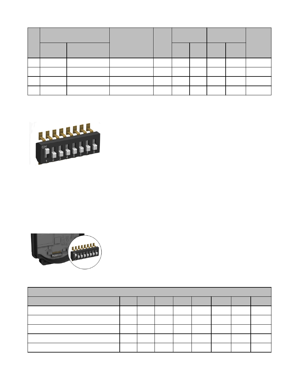
Accessing the DIP Switches
To access the DIP switches, follow these steps:
1. Unscrew the four screws that mount the cover to the bottom housing.
2. Remove the cover from the housing without damaging the ribbon cable or the pins the cable plugs into.
3. Gently unplug the ribbon cable from the board mounted into the bottom housing. For integrated battery models (no ribbon cable) and
Class I, Division 2 certified devices (ribbon cable is glued down), skip this step.
4. Remove the black cover plate from the bottom of the device's cover.
The DIP switches are located behind the rotary dials. After making the neces-
sary changes to the DIP switches, place the black cover plate back into posi-
tion and gently push into place. Plug the ribbon cable in after verifying that
the blocked hole lines up with the missing pin. Mount the cover back onto the
housing.
DIP Switch Settings
Switches
Device Settings
1
2
3
4
5
6
7
8
Rotary dial address mode
OFF*
Extended address mode
ON
Inputs sourcing (PNP)
OFF*
Inputs sinking (NPN)
ON
Node 1 baseline filter OFF
OFF*
SureCross DX80 Gateway with Discrete I/O
6
www.bannerengineering.com - tel: 763-544-3164
P/N 139075 rev. D