Dimensions – Banner SI-HG63 Hinge Style Switches User Manual
Page 11
Example
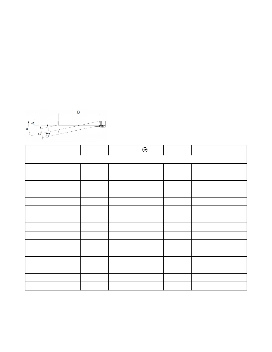
A guard with a 40 mm aluminum profile (A) and a width of 900 mm (B) is safeguarded by SI-HG63.. safety interlocking switch. The
switching point is set (fixed) while guard is closed, the positive-opening switching point is set at α = 6° in the opening direction (assuming
that the point has not been finely-adjusted).
In the table, find the "B" row of "900" and then follow over to the 6° column and note the number (94.1 mm). The approximate opening in
the guard at the switching point (C1) can be found by subtracting the width of the guard.
C1 = C – A = 94.1 mm – 40 mm = 54.1 mm (at initial installation).
where:
α = Opening angle of the guard at the point of switching
A = Width of the guard in mm
B = Length of the guard in mm
C = Distance travel by outside of guard
C1 = Size of the opening in the guard at the point of switching
α
3°
4°
5°
6°
7°
8°
9°
B mm
C mm
100
5.2
7.0
8.7
10.5
12.2
13.9
15.6
200
10.5
14.0
17.4
20.9
24.4
27.8
31.3
300
15.7
20.9
26.1
31.4
36.6
41.8
46.9
400
20.9
27.9
34.9
41.8
48.7
55.7
62.6
500
26.2
34.9
43.6
52.3
60.9
69.6
78.2
600
31.4
41.9
52.3
62.7
73.1
83.5
93.9
700
36.6
48.8
61.0
73.2
85.3
97.4
109.5
800
41.9
55.8
69.7
83.6
97.5
111.3
125.1
900
47.1
62.8
78.4
94.1
109.7
125.3
140.8
1000
52.3
69.8
87.2
104.5
121.9
139.2
156.4
1100
57.6
76.7
95.9
115.0
134.1
153.1
172.1
1200
62.8
83.7
104.6
125.4
146.2
167.0
187.7
1300
68.0
90.7
113.3
135.9
158.4
180.9
203.4
1400
73.3
97.7
122.0
146.3
170.6
194.8
219.0
1500
78.5
104.6
130.7
156.8
182.8
208.8
234.7
Dimensions
For blank hinge dimensions, see
on page 13.
Hinge Wing Safety Interlock Switches
Datasheet
129465_web Rev.
D
www.bannerengineering.com - tel: 763-544-3164
11