Banner SureCross DX80 Wireless Networks User Manual
Page 4
Threshold and Hysteresis (M-GAGE)
Threshold and hysteresis work together to establish the ON and OFF points of an analog input. The threshold defines a trigger point or
reporting threshold (ON point) for a sensor input. Setting a threshold establishes an ON point. Hysteresis defines how far below the
threshold the analog input is required to be before the input is considered OFF. A typical hysteresis value is 10% to 20% of the unit’s
range.
The M-GAGE Node’s threshold and hysteresis ranges are 0 to 65,535. The factory default threshold setting is 100 and default hysteresis
is 30 (the sensor detects an OFF condition at threshold minus hysteresis, or 100 - 30 = 70). With the default settings, once the magnetic
field reading is above 100, an ON or “1” is stored in the lowest significant bit (LSB) in the Modbus register. When the M-GAGE reading
drops below the OFF point (threshold minus hysteresis), the LSB of the Modbus register is set to “0.” To determine your threshold, take
M-GAGE readings of the test objects at the distance they are likely to be from the sensor. For example, if a car reads 100, a bicycle 15,
and a truck reads 200, setting the threshold to 150 will detect only trucks of a specific size. Magnetic field fluctuations vary based on the
amount of ferrous metal present and the distance from the sensor.
Wiring Your SureCross® Device
Use the following wiring diagrams to first wire the sensors and then apply power to the SureCross devices.
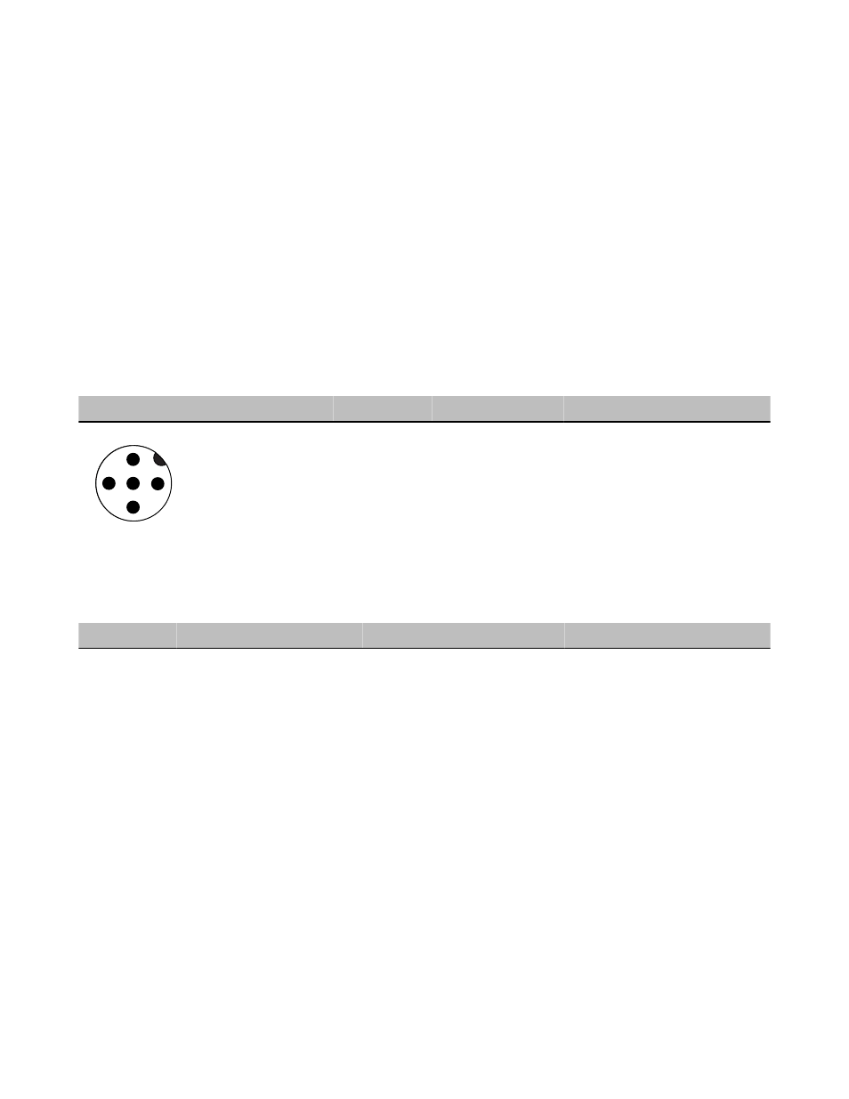
5-pin Euro-Style Hookup
Wiring the 5-pin Euro-style connector depends on the model and power requirements of the device. Connecting dc power to the commu-
nication pins will cause permanent damage.
Wire No.
Wire Color
Description
1
2
3
4
5
1
Brown
10 to 30V dc
2
White
RS485 / D1 / B / +
3
Blue
dc common (GND)
4
Black
RS485 / D0 / A / –
5
Gray
Comms Gnd
DX80...C Wiring
Wiring power to the DX80...C models varies depending the power requirements of the model. Connecting dc power to the communication
pins (Tx/Rx) will cause permanent damage. For FlexPower devices, do not apply more than 5.5V to the gray wire.
Terminal Label Gateway, DX85
10 to 30V dc Powered Nodes
Battery Powered Nodes
V+
10 to 30V dc
10 to 30V dc
Tx/+
RS485 / D1 / B / +
V-
dc common (GND)
dc common (GND)
dc common (GND)
Rx/-
RS485 / D0 / A / -
B+
3.6 to 5.5V dc
SureCross DX80 Gateway for M-GAGEs
4
www.bannerengineering.com - tel: 763-544-3164
P/N 134303 Rev. H