Surecross™ dx80k wireless configured kit, Hookup diagrams, Configured input/output mapping – Banner SureCross DX80 Wireless Networks User Manual
Page 2: Extended i/o
Banner Engineering Corp. • Minneapolis, MN U.S.A
www.bannerengineering.com • Tel: 763.544.3164
2
P/N 136442
rev. A
SureCross™ DX80K Wireless Configured Kit
For additional information, including installation and setup, weatherproofing, device menu
maps, troubleshooting, and a list of accessories, please refer to the SureCross™ DX80
Wireless I/O Network product manual, Banner p/n 132607.
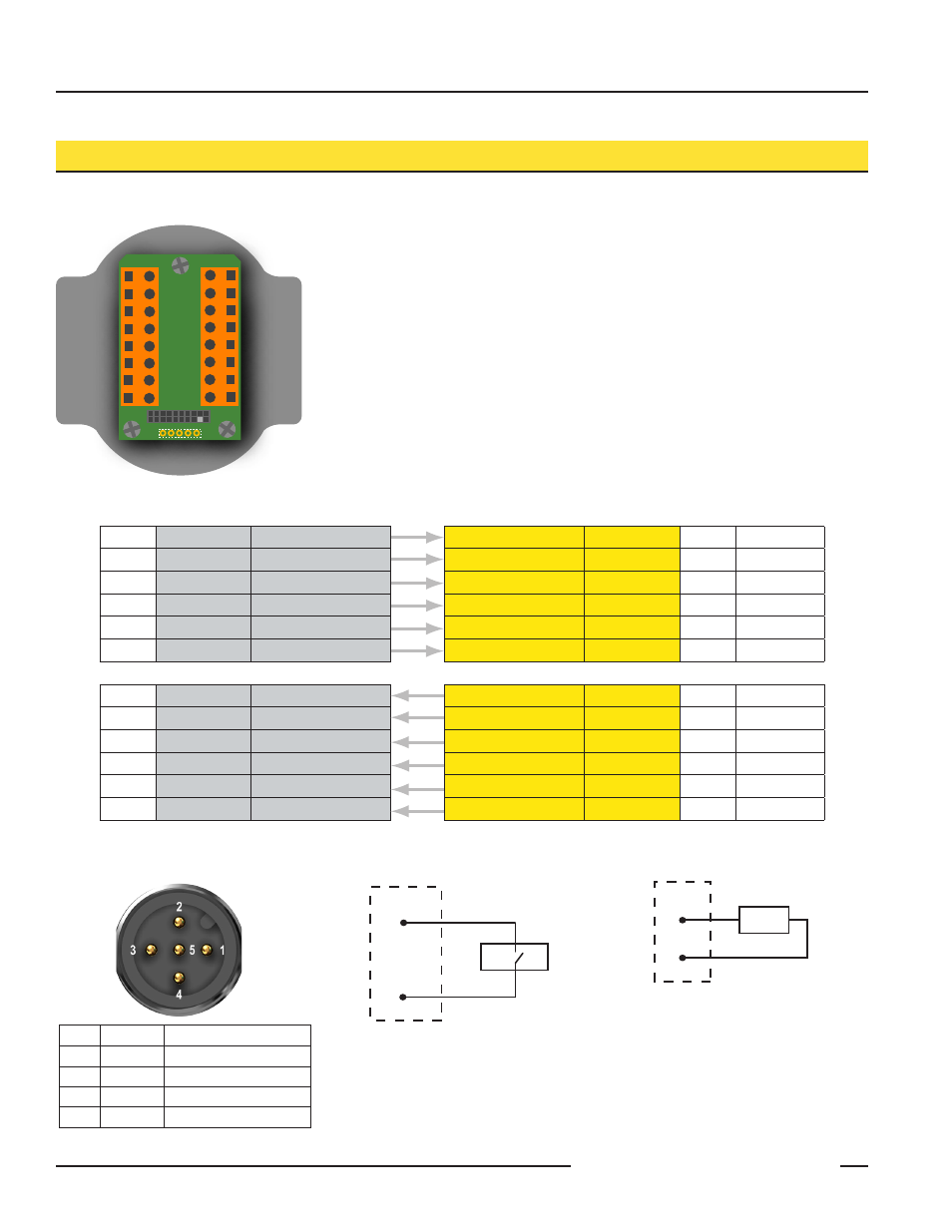
Hookup Diagrams
1
Brown
10 to 30V dc Input
2
White
RS485 / D1 / B /+
3
Blue
dc common (GND)
4
Black
RS485 / D0 / A / -
5
Gray
Comms Gnd
5-pin M12 Euro Hookup
Sourcing Input Wiring
Sourcing Output Wiring
I/O
Point
Terminal
Block Label
DX80 Gateway
DX80 Node
Terminal
Block Label
I/O
Point
1
DI1
Discrete IN 1
Baseline Command
14
Node 1
2
DI2
Discrete IN 2
Baseline Command
14
Node 2
3
DI3
Discrete IN 3
Baseline Command
14
Node 3
4
DI4
Discrete IN 4
Baseline Command
14
Node 4
5
DI5
Discrete IN 5
Baseline Command
14
Node 5
6
DI6
Discrete IN 6
Baseline Command
14
Node 6
9
DO1
Discrete OUT 1
M-GAGE IN 1
DI1
1
Node 1
10
DO2
Discrete OUT 2
M-GAGE IN 1
DI1
1
Node 2
11
DO3
Discrete OUT 3
M-GAGE IN 1
DI1
1
Node 3
12
DO4
Discrete OUT 4
M-GAGE IN 1
DI1
1
Node 4
13
DO5
Discrete OUT 5
M-GAGE IN 1
DI1
1
Node 5
14
DO6
Discrete OUT 6
M-GAGE IN 1
DI1
1
Node 6
Configured input/output mapping
PWR
GND
DO6
DO5
DO4
DO3
DO2
DO1
PWR
GND
DI6
DI5
DI4
DI3
DI2
DI1
Extended I/O
Terminal Block
P2
G B - W +
DIx
PWR
Sourcing Input Wiring
sensor
SureCross
Device
output
DOx
GND
Sourcing Output Wiring
SureCross
Device
load
input