Overview, 5 control mode selection – Banner EZ-ARRAY USB Serial Adapter User Manual
Page 6
4
P/N 126701
Banner Engineering Corp.
•
Minneapolis, U.S.A.
www.bannerengineering.com • Tel: 763.544.3164
A-GAGE EZ-ARRAY
QuickStart Guide
Overview
Three-Digit Display
The 3-digit display has slightly different functions during
normal operation, alignment, and gain adjust modes. In normal
operation the display indicates current numerical value of the
measurement mode for analog output 1. The display also
identifies the following activated sensor functions: blanking and
locked-out user interface/electronic configuration, as shown in
Figure 1-4. (For information on inverting the display, see Section
4.4 or 5.)
During blanking mode, the display reads “n”, followed by the
number of blocked beams in the array. During alignment mode, it
reads “A”, followed by the number of blocked, unblanked beams;
a period follows the A (“A.”) if blanking is configured.
During gain adjust mode, the display reads “
l
” followed by “1” or
“2” to indicate the gain level. (A “1” represents high excess gain,
and a “2” represents low contrast.)
If a sensing error occurs, the display reads “c” followed by a
number that corresponds to the recommended corrective action
(see Section 4.6).
Blanking Indicator
The Blanking indicator will be visible (ON) whenever the user
has enabled the blanking feature. It appears as a period
following the first digit of the display.
Electronic Configuration Indicator
The Electronic Configuration indicator is ON when the sensor
configuration is not defined by the receiver interface, but by
the GUI (this is set via the GUI). When electronic configuration
is enabled, the receiver interface DIP switch and push button
settings are ignored.
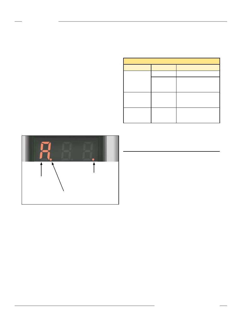
Figure 1-4. Indications provided by the 3-digit display
1.5 Control Mode Selection
The control mode determines the method used to control
scanning of the light screen array. Choose from two control
modes: continuous scan mode and gate mode (which itself has
four options). Continuous scan is automatically selected when
the receiver interface is used for configuration.
In Continuous Scan Mode, the receiver begins a new scan as
soon as it updates the outputs from the previous scan. This is
the fastest scan control method; it is used in most analog output
applications and whenever continuous updating of the outputs is
acceptable. It is available via either the receiver interface or the
GUI.
Gate Mode can be selected via the GUI only. It uses the
receiver Teach (gray) wire to provide a gate input pulse from
(typically) a dc device, such as an NPN-output photoelectric
sensor or a PLC discrete output. Refer to Section 5 for more
information.
Gate mode has four options:
• Gate ON: the receiver will scan as long as the gate is active.
• Gate OFF: the receiver will scan whenever the gate is not
active.
• Gate rising edge: the receiver will scan once for each gate
transition from falling edge to rising edge.
• Gate falling edge: the receiver will scan once for each gate
transition from rising edge to falling edge.
Receiver Interface Status Indicators
LED Indicator
Color
Explanation
System Status
Green
System is OK
Red
Marginal Alignment or
Hardware Error;
check 3-digit display*
Modbus
Activity
Yellow ON or
Flashing
Activity detected on the
modbus communication
channel
Modbus Error
Red
Communication Error:
Check cabling or modbus
master controller
* Display shows “
c”: See Section 4.6.
Display shows only numbers: Low Gain/Marginal Alignment
condition. See Section 4.6.
Receiver Interface Status Indicators
The receiver has three status indicators: green/red System
Status, yellow Modbus Activity, and red Modbus Error. The
following table lists the indicator states.
Period ON indicates
Blanking Configured
‘A’ in this
position indicates
Alignment mode
Period ON indicates
Electronic Configuration
Enabled