Installation, 4 optical alignment – Banner EZ-ARRAY USB Serial Adapter User Manual
Page 20
18
P/N 126701
Banner Engineering Corp.
•
Minneapolis, U.S.A.
www.bannerengineering.com • Tel: 763.544.3164
A-GAGE EZ-ARRAY
QuickStart Guide
Installation
3.4 Optical Alignment
After the electrical connections are made, power up the emitter
and receiver. Verify that input power is present to both emitter
and receiver; the emitter Status indicator and the receiver Status
LED should be ON green. If the receiver Status LED is on red
(and a “c” appears on the 3-digit display), refer to Section 4.6.
NOTE: At power-up, all Zone indicators are tested (flash
red), then the number of blocked beams is displayed.
Observe the receiver indicators.
Possible Indicator Combinations
The 3-digit display shows the number of blocked beams
Zone indicator(s) red: beams in that zone blocked (not
blanked)
Zone indicator(s) green: all beams in that zone made or
blanked
• Aligned and Clear (Run) condition – the receiver Status
indicator and Zone indicators all ON green. The 3-digit display
reads 0.
• Partial Alignment – the receiver Status indicator remains ON
green. Some Zone indicators are red to designate areas where
the beams are not made (are out of alignment or blocked).
The 3-digit display reads the number of blocked/mis-aligned
beams.
• Out of Alignment – the receiver Status indicator remains ON
green. All Zone indicators are red, to designate that some
beams are blocked in each zone. The 3-digit display reads the
total number of beams in the array.
Optimize Alignment and Maximize Excess Gain
Verify that the emitter and receiver are pointed squarely
at each other. A straightedge (e.g., a level) can determine the
direction the sensor is facing (see Figure 3-7).
Slightly loosen the sensor mounting screws and rotate one
sensor to the left and right, noting the positions where the
receiver Zone indicators turn from green to red; repeat with the
other sensor. Center each sensor between the noted positions
and tighten the end cap mounting screws, making sure to
maintain the positioning. The sensor windows should directly
face each other.
Once optimum optical alignment is verified, proceed to
configuration, via the receiver interface, the remote teach wire
or the GUI (Section 4.2 or 5 of the full manual) and complete
the electronic alignment. This further alignment step adjusts the
emitted light level of each beam for the application, to complete
the alignment process.
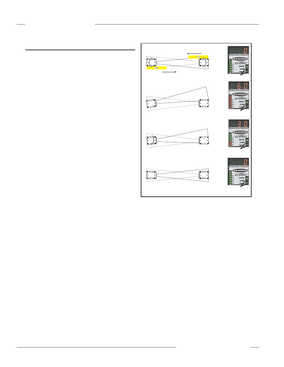
Figure 3-7. Optimizing optical alignment; 300 mm model shown
Straightedge
Straightedge
a)
b)
c)
d)
OFF
OFF
OFF
OFF
0 beams blocked; all Zone indicators ON Green
60 beams blocked; all Zone indicators ON Red
30 beams blocked; 4 Zone indicators ON Green, 3 ON Red
0 beams blocked; all Zone indicators ON Green