Installation, 3 hookups, 1 serial connection – Banner EZ-ARRAY USB Serial Adapter User Manual
Page 19: 2 inputs, 3 outputs, 4 synch (pink) wire, Discrete outputs, A-gage ez-array, Figure 3-5. npn hookup
P/N 126701
17
Banner Engineering Corp.
•
Minneapolis, U.S.A.
www.bannerengineering.com • Tel: 763.544.3164
A-GAGE EZ-ARRAY
QuickStart Guide
Installation
wh
wh
ye
ye
gn
gn
rd
rd
gy
0-2V dc
gy
bare
bare
pk
bu
bn
pk
bu
bn
Sync
Power Supply V+
10-30V dc
Power
Power Supply V-
Sync
Power Supply V+
Power Supply V-
V Out 1
V Out 2
Out 1
Out 2
Teach
Shield
Shield
Receiver
Emitter
Load
Load
+
–
+
–
+
–
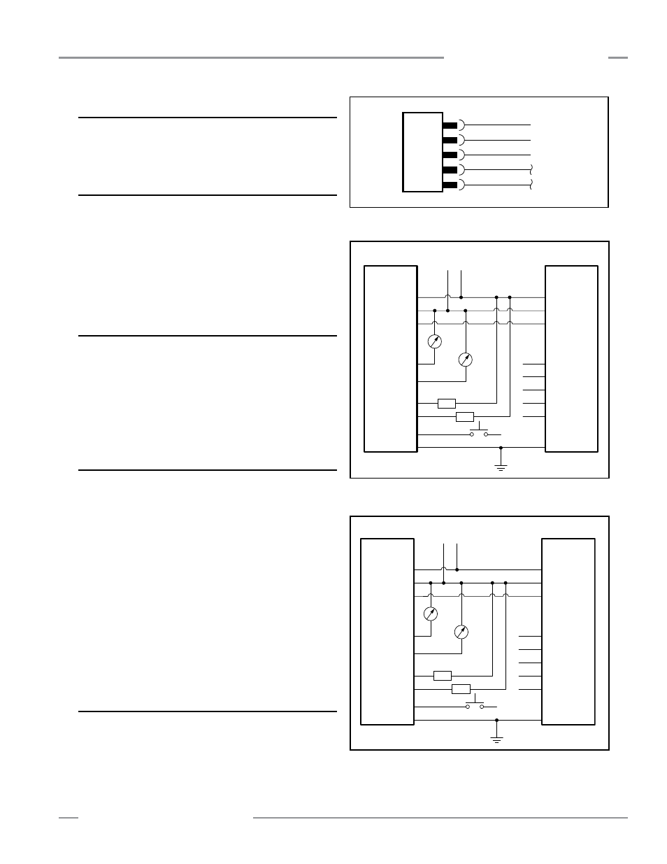
Figure 3-5. NPN hookup
Receiver
Emitter
wh
wh
ye
ye
gn
gn
rd
rd
gy
0-2V dc
gy
bare
bare
pk
bu
bn
pk
bu
bn
Sync
Power Supply V+
Power Supply V-
Sync
Power Supply V+
Power Supply V-
V Out 1
V Out 2
Out 1
Out 2
Teach
Shield
Shield
Load
Load
+
–
+
–
10-30V dc
Power
+
–
Figure 3-6. PNP hookup
Figure 3-4. Serial communication hookup
3.3 Hookups
Refer to Figures 3-4, 3-5 and 3-6 for the appropriate hookup
information.
3.3.1 Serial Connection
This connection is used only when the GUI is also used. The
receiver has a Modbus RTU-485 serial interface. A separate
5-pin Euro-style connection is provided at the opposite end of
the power cable connection, to electrically connect the serial
communication cable to an external PC or PLC. Refer to Figure
3-4; the white wire is connected to the Modbus D1/B/+ terminal
and the black wire is connected to the D0/A/— terminal.
3.3.2 Inputs
Refer to Figures 3-5 and 3-6 for standard hookup information.
Receiver gray wire: The receiver has an input that can be used
as a gate input or for remote teach. To initiate remote teach
functions, tie the wire through a switch to sensor common. To
initiate sensor scans (gate input) using this wire, see Section 5
of the full manual for more information.
3.3.3 Outputs
Refer to Figures 3-5 and 3-6 for standard hookup information
and Section 2.6 Sensor Specifications for further electrical
requirements.
Analog white and yellow wires: The receiver has two analog
outputs. Depending on receiver model, both outputs are either
voltage or current. The white wire is referenced as analog output
1; the yellow wire is referenced as analog output 2. Both analog
current and voltage will source current through an external load
to sensor common.
Discrete Outputs
The receiver has two discrete outputs; the green wire referenced
as discrete #1, and the red wire, discrete #2. Depending on
model, both outputs are either NPN or PNP. Refer to Section 2.6
Specifications for further electrical requirements.
3.3.4 Synch (Pink) Wire
The emitter and receiver are electrically synchronized via the
pink wire. The emitter and receiver pink wires must only be
electrically connected together.
Modbus
white
black
blue
D1/B/+
D0/A/–
common
brown
gray