Overview, 1 features – Banner EZ-ARRAY USB Serial Adapter User Manual
Page 3
P/N 126701
1
Banner Engineering Corp.
•
Minneapolis, U.S.A.
www.bannerengineering.com • Tel: 763.544.3164
A-GAGE EZ-ARRAY
QuickStart Guide
Overview
The A-GAGE™ EZ-ARRAY™ measuring light screen is ideal
for applications such as on-the-fly product sizing and profiling,
edge-guiding and center-guiding, loop tensioning control,
hole detection, parts counting, and similar uses. Emitters
and receivers, with arrays available in 10 lengths from 150 to
1800 mm (5.9" to 70.9") long, feature a closely spaced column
of beams to provide a precise light screen for measuring
applications at a working range of 400 mm to 4 m (16" to 13').
Its two-piece design makes it economical and easy to use.
Controller functionality is built into the receiver housing. It can
be configured for many straightforward applications simply
by configuring the six-position DIP switch on the front of the
receiver (the receiver user interface). For more advanced
control, easy-to-use graphic user interface (GUI) software is
available on the included CD to configure the sensors using a
PC.
This QuickStart Guide provides setup and use instructions when
the receiver interface is used. Instructions for using the GUI
are in Section 5 of the full manual (p/n 130426), found on the
included CD or online at
www.bannerengineering.com/130426
.
Installation is easy, too. The emitter and receiver housings can
be side-mounted or end-cap-mounted using the included end-
cap brackets; longer models also include a center bracket (see
Section 3.1).
1. Overview
Beam synchronization is achieved via the 8-conductor sensor
cables. Individual LEDs and a 3-digit diagnostic display on the
receiver provide ongoing visual sensing status and diagnostic
information. Comprehensive data is available to a process
controller via a combination of five outputs: two analog, two
discrete, and one serial.
1.1 Features
Built-in features in the EZ-ARRAY contribute to its ease of
use. Many features are available using either the user-friendly
receiver interface or the more advanced GUI software interface.
Built-in diagnostic programming and easy-to-see indicators on
the receiver simplify physical alignment and troubleshooting
(Figure 1-1); advanced diagnostics are available on the GUI.
The receiver has a bright LED that indicates overall sensing
status (OK, marginal alignment, and hardware error). Two
more LEDs indicate serial communication status. Seven Zone
indicators each communicate the blocked / aligned status of one-
seventh of the total array. A 3-digit diagnostic display provides
further diagnostic information, including number of beams
blocked, whether blanking is configured, and troubleshooting
codes.
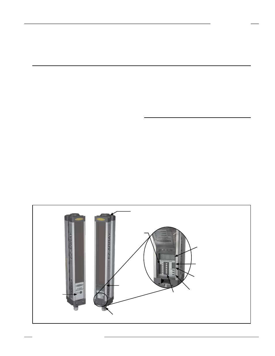
Figure 1-1. A-GAGE EZ-ARRAY features
Beam #1
(Closest to
Display)
Power ON
LED
Emitter
Receiver
3-Digit
Diagnostic
Display
Screw-on Security Plate limits
access to DIP switch and push
buttons
Zone
Indicators
Gain (Sensitivity Adjust)
Push Button
6-Position
DIP Switch
Alignment/Blanking
Push Button
Connection to 5-pin Communication Cable
Under Hinged Access Panel:
Status, Communication Active,
and Communication Error LEDs