Bird Technologies SCC7 Series-Manual User Manual
Page 30
16
11. Connect the ground wire to the top cover.
12. Install the top cover.
13. Secure it with the four screws removed earlier.
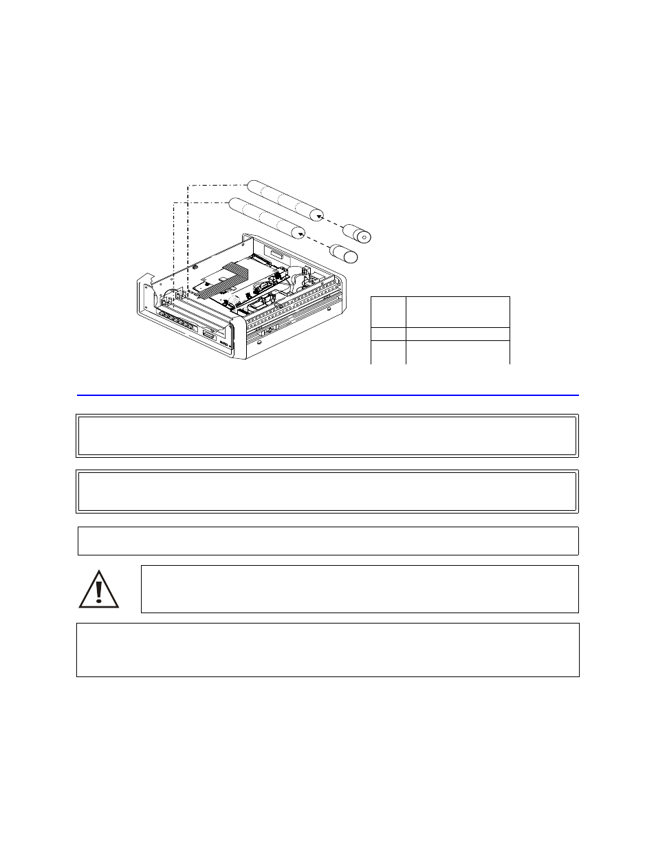
Figure 9 Batteries
Replacing the Power Sensor
Removing the Power Sensor
1.
Disconnect the RF line from the Cal Cart.
2.
Disconnect AC power line.
3.
Remove the Cal Cart front panel. See “Removing the Front Panel” on page 4.
4.
Remove the tamper seal from the 7/16 DIN connector nut.
WARNING
To avoid personal injury, disconnect the power cord from the AC line before performing any maintenance,
including fuse replacement.
WARNING
Never attempt to connect or disconnect RF equipment from the transmission line while RF power is being applied.
Leaking RF energy is a potential health hazard.
CAUTION
The Bird 4421 must be powered off when connecting or disconnecting the power sensor from the power meter.
CAUTION
Changing the sensor’s connectors will invalidate calibration data, and may reduce the maximum
power rating of the unit.
CAUTION
Due to the complexity of the Bird Power Sensor, field repairs beyond general maintenance should not be
attempted.
Removal or disturbance of the power sensor cover can result in cancellation of lifetime warranty.
X4
X4
Ite
m
Description
1
Battery retaining belt
2
Battery tube
(batteries inside)