Bird Technologies SCC7 Series-Manual User Manual
Page 26
12
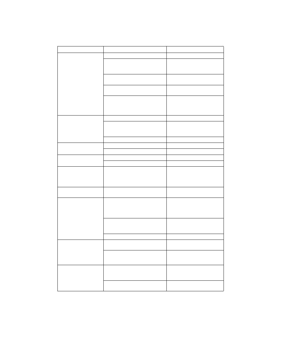
PROBLEM
POSSIBLE CAUSE
CORRECTION
Power meter has no
power
The batteries are dead.
Recharge the batteries
The power meter’s AC power
cord is disconnected from the
terminal strip.
Connect the power cord
The Cal Cart’s AC power cord is
not connected to the AC line.
Connect AC power
The ON/OFF rocker switch on
the rear panel is set to OFF.
Set the switch to ON
The power meter fuse is blown.
Note:
Unplug the Cal Cart to
check the fuse.
Replace fuse. See “Replacing
the Power Meter Fuse” on
page 15.
Dash moves across the
display
The AC power cord is defective.
Replace AC power cord
The sensor cable is disconnected
from both the power meter and
power sensor.
Connect sensor cable
The sensor cable is defective.
Replace sensor cable
Display blank or not
updating
The batteries are not charged.
Recharge the batteries.
The meter is defective.
Return meter for service.
Power meter turns off
while on battery power
“LO BAT” is displayed.
Recharge the battery.
The meter is defective.
Return meter for service.
Push buttons do not
respond when tested.
See “Push Button Test”
on page 13.
The push buttons are defective.
Return meter for service.
Every segment on the
display is lit.
The meter is defective.
Return meter for service
IEEE-488 Interface
Module does not
respond to the interface
link
Are the address in the interface
program and the address setting
on the DIP switches on the
interface module the same?
Change the program or DIP
switch setting so that the
addresses are the same (see
“Dip Switch” on page 14)
Send the “J0” self test command,
then check the status. Does the
power meter fail the self test?
Replace interface module
Is the IEEE cable defective?
Replace IEEE interface cable
RS-232 Interface
Module does not
respond to the interface
link. Fails J0 self-test
command.
Are the DIP switches set
correctly?
Set DIP switches
Is the RS-232 cable defective?
Replace RS-232 interface
cable
With the RS-232
module installed, the
power meter displays
“TALK” but does not
operate as expected.
Is DIP switch 2 set correctly?
For “talk/listen” operation, set
this switch to ON. For “talk
always” set this switch to OFF.
Is DIP switch 1 set correctly?
Set DIP switch 1 as indicated
in Figure 25