Rockwell Automation 440F MatGuard, 440F-C4000 Mat Controllers User Manual
Page 25
After completion of the design of the safety related control system ensure that the response time
assumed at 5.4.1 remains valid. If the value changes, it will be necessary to repeat the safety distance
calculations.
Next consider the options for reset. The consequences of the reset scheme selected should be carefully
considered for hazards caused by unexpected start up etc., both under normal conditions and under fault
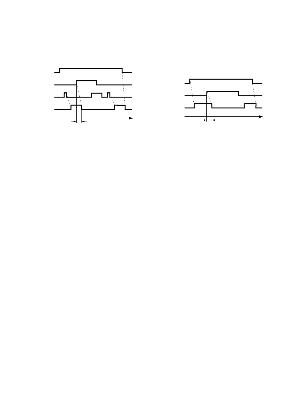
conditions. Timing diagrams are given below for both modes of the mat system.
Fig 19 Manual reset mode
Fig 20 Auto reset mode
Relationship between actuation, reset and output.
Relationship between actuation and output
MANUAL RESET MODE
The reset can be accomplished by the button on the control unit or by a remote push button or by
voltage free contacts within the machine safety related control system. The outputs of system will remain
off until reset after power up and may require master/slave reset circuits in complex systems where other
power up interlocks (start interlocks) are present.
AUTO RESET MODE
When used in the auto reset mode, the machine’s control system will need a separate reset function to
prevent machine start up when stepping off the mat or after a temporary power supply failure or dip.
SELECTING THE POWER SUPPLY
The system offers four possibilities for power supply and in virtually every case a suitable supply will be
available from the machine. Check that the power supply parameters conform with the requirements of
mat system as given in the specification. Where a 24V AC or DC supply is used it must be isolated from
the mains supply in accordance with international electrical safety practice (IEC 364-4-41). One pole
should be earthed (negative to be earthed for DC supplies). If special arrangements have to be made,
commercial units supplying 24V DC to suit the system are readily available.
AUXILIARY OUTPUT
This is a non-safety output provided as a status output. It is particularly useful in systems using PLC
functional machine control in combination with hard wired safety circuits as a status import to the PLC.
Other uses include diagnostics in protection schemes and/or driving status lamps or alarms. The safety
function must not depend on this output.
ARC SUPPRESSION
Arc suppression networks or devices are recommended for all inductive loads. For safety circuits,
suppressors should be fitted across the load and never across the contacts. The type and ratings of the
suppressors will be determined by the supply and load characteristics. Note that suppressors can
increase response time, particularly suppressor diodes across DC coils, and should be in place when
measuring response times.
CONTROL UNIT
SAFETY OUTPUTS
POWER TO
CONTROL UNIT
ACTUATING
FORCE
TIME
20ms
Response time
CONTROL UNIT
SAFETY OUTPUTS
POWER TO
CONTROL UNIT
RESET
ACTUATING
FORCE
TIME
20ms
Response time
24