K1 k2 – Rockwell Automation 440F MatGuard, 440F-C4000 Mat Controllers User Manual
Page 24
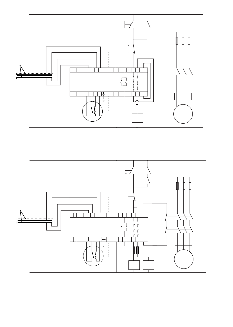
Fig. 17
Example connection diagram showing application with single contactor (single channel),
440F-C4000D. Circuit status - Supply power ON - No presence on sensor mat - Reset button operated (if
in manual reset mode) - Machine start circuit enabled.
NOTE: If the contactor sticks ON - the motor will not stop when the mat is stood on.
Fig. 18
Example connection diagram showing application with two contactors and contactor
monitoring (dual channel), 440F-C4000D.
Circuit status - Supply power ON - No presence on sensor mat - Reset button operated (if in manual
reset mode) - Machine start circuit enabled.
NOTE: If either of the contactors stick ON - the motor will stop when the mat is stood on and the fault
will be detected.
M
K1
K2
24VDC, SUPPLY
L1
L2
L3
AUXILIARY OUTPUT
AUXILIARY INPUT
K1
(AUX)
K2
(AUX)
START
MOMENTARY
PUSH
BUTTON
STOP
MOMENTARY
PUSH
BUTTON
FUSES
MOTOR
PROTECTION
E.G. THERMAL
CUT OUT
+
1
2
3
4
31
MC
MC
13 23
32
14 24
CONTROL UNIT
K1
K2
–
POSITIVELY
GUIDED
CONTACTOR
AUXILIARY
CONTACTS
A1
A2
WHITE
WHITE
BLACK
BLACK
IND
SENSOR MATS
INTERNAL SENSOR
MAT PLATES
RESET
RESET
Y6
Y4
Y2
IND
Y1 Y3 Y5
110VAC, 230VAC SUPPLY
(ALTERNATIVE SUPPLY CONNECTION)
M
K1
24VDC, SUPPLY
L1
L2
L3
AUXILIARY OUTPUT
AUXILIARY INPUT
K1
(AUX)
START
MOMENTARY
PUSH
BUTTON
STOP
MOMENTARY
PUSH
BUTTON
FUSE
MOTOR
PROTECTION
E.G. THERMAL
CUT OUT
+
1
2
3
4
MC
CONTROL UNIT
K1
–
WHITE
WHITE
BLACK
BLACK
SENSOR MATS
INTERNAL SENSOR
MAT PLATES
A1
A2
LINK
LINK
31
13 23
32
14 24
RESET
IND
IND
RESET
Y6
Y4
Y2
Y1 Y3 Y5
MC
110VAC, 230VAC SUPPLY
(ALTERNATIVE SUPPLY CONNECTION)
23