Rockwell Automation SA3100 Diag,Troublesht,Startup,Guide User Manual
Page 27
PMI Regulator Operating Modes
3-5
If the Power Module and the motor are connected through one set of leads,
disconnect the motor leads from the Power Module. You will need to
connect the voltmeter directly to the phase U, V, and W outputs of the Power
Module.
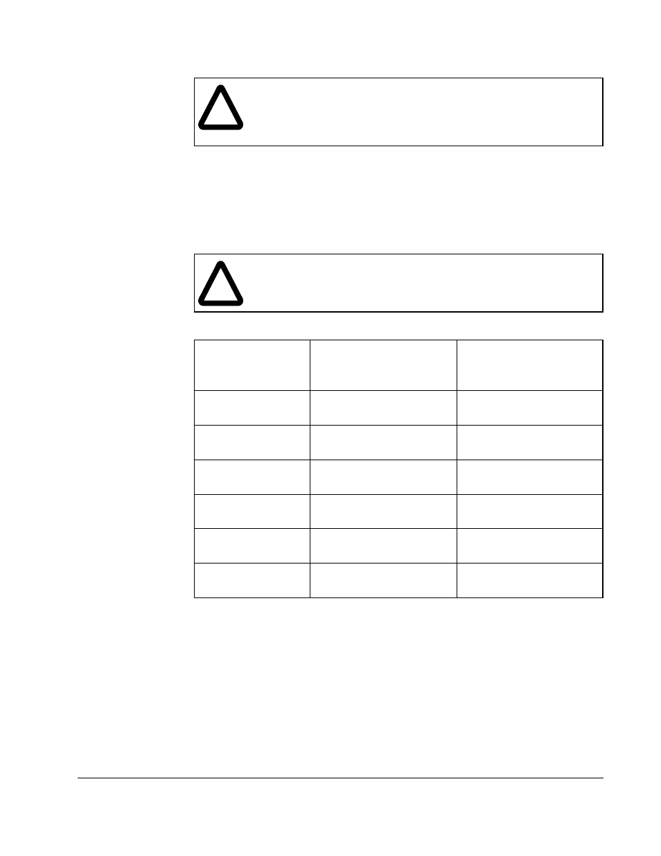
Step 6. Use table 3.2 to determine the devices to be tested and to identify where to
connect the voltmeter. See figure 3.2. Set the voltmeter to the 1000V scale.
!
ATTENTION:The bridge test applies the full DC bus voltage to an output
phase for the duration of a test. The motor must not be connected to the
Drive while performing the bridge test in order to avoid damage to the
drive and motor. Failure to observe this precaution could result in damage
to, or destruction of, the equipment.
!
ATTENTION:The remaining steps are performed with power on.
Exercise extreme caution as hazardous voltages exist. Failure to
observe this precaution could result in severe bodily injury or loss of life.
Table 3.2 – Bridge Test Connections
Power Device Pair
Being Tested
1
1. It is not necessary to measure all the power device pairs. All possible combinations can be tested by
testing either pairs 1 through 4 or 3 through 6.
Bridge Test Code
Register (105/1105)
Value
2
2. With the bridge test enabled, enter successive values into register 105/1105 to test different device pairs
without re-enabling the bridge test.
Voltmeter Connection
for +VDC
3
3. With the bridge test enabled, approximately the nominal bus voltage should be measured across each
pair.
1.
U upper
V lower
11H
U(+)
V(–)
2.
U lower
W upper
0CH
U(–)
W(+)
3.
U upper
W lower
21H
U(+)
W(–)
4.
U lower
V upper
0AH
U(–)
V(+)
5.
V upper
W lower
22H
V(+)
W(–)
6.
V lower
W upper
24H
V(–)
W(+)