Rack 10: info, Table 16 rack 10: info descriptions, Table 17 rack 10: module mode descriptions – Rockwell Automation T8449 Trusted TMR 24V dc Valve Monitor Module - 40 Channel User Manual
Page 31: Trusted, Module t8449
Trusted
TM
Module T8449
Issue 13 Apr 10
PD-T8449
31
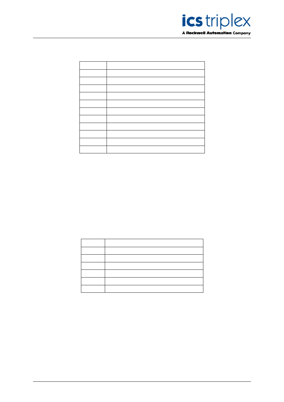
3.2.10. Rack 10: INFO
The Information board supplies the user with information about the general health and status of the
module.
Channel
Description
1
Active Module chassis number
2
Active Module slot number
3
Active Module Healthy
4
Active Module Mode
5
Standby Module Chassis Number
6
Standby Module Slot Number
7
Standby Module Healthy
8
Standby Module Mode
9
FCR Status
10
Primary module is active
11
Active module is simulated
Table 16 Rack 10: INFO descriptions
The active module chassis and slot numbers indicate the position of the currently active module.
These values will change to match the primary or secondary module position, depending on their active
status, i.e. active/standby changeover will “swap” the values for the active module chassis and slot
number channels with those in the standby module chassis and slot number channels. The chassis
and slot numbers are set to zero if the module is not present.
The Active and Standby module healthy channel is returned as an integer, however only the least
significant bit is used. A value of 0 indicates that a fault has been detected, a non-zero value indicates
that the module is healthy.
The Active and Standby Module Mode is an integer indicating the current operating mode of the
associated module. The value indicates the current internal operating mode of the module.
Value
Module Mode
5
Shutdown
4
Maintain
3
Active
2
Standby
1
Configuration
0
Unknown, no module present
Table 17 rack 10: Module Mode descriptions