Rack 1: do_test, Rack 2: state, Table 5 rack 1: do_test descriptions – Rockwell Automation T8449 Trusted TMR 24V dc Valve Monitor Module - 40 Channel User Manual
Page 24: Table 6 rack 2: state descriptions, Trusted, Module t8449
Trusted
TM
Module T8449
Issue 13 Apr 10
PD-T8449
24
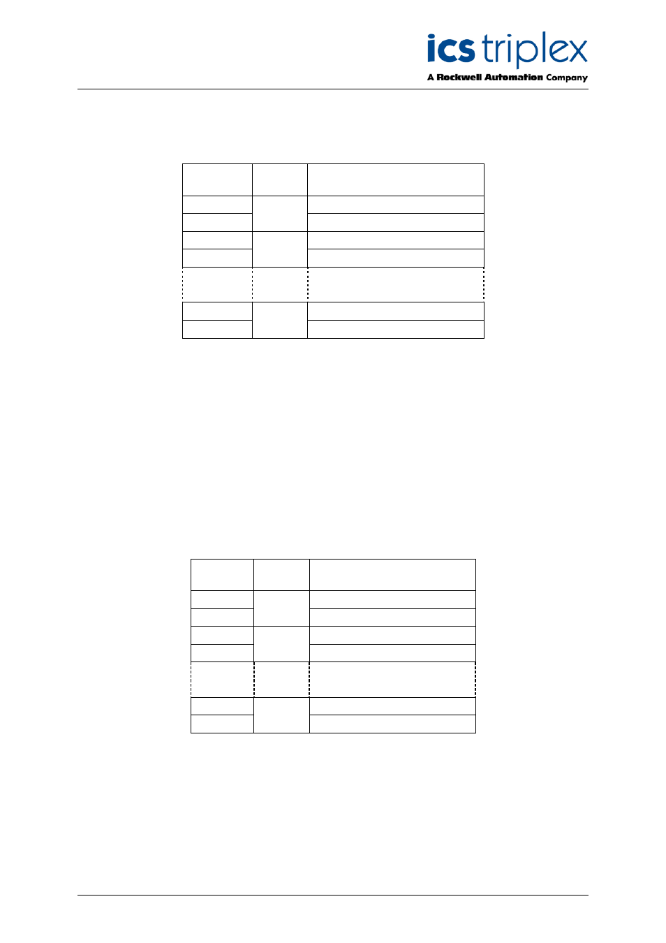
3.2.1. Rack 1: DO_TEST
This board provides the connection to the logical output control signal for each of the field devices as
well as the valve test initiation signal.
Channel
Field
Device
Description
1
Control output command
2
1
Test initiation command
3
Control output command
4
2
Test initiation command
39
Control output command
40
20
Test initiation command
Table 5 Rack 1: DO_TEST descriptions
The user application should set the control output control signal to true (logic ‘1’) to turn ON or energise
an output, and false (logic ‘0’) to turn OFF or de-energise an output.
A valve test will be initiated on each rising edge of the test initiation signal when it is set to true (logic
‘1’). A falling edge of the test initiation signal when it is set to false (logic ‘0’) will reset the valve test and
clear all internal valve test data (such as the Valve Test State, Test Time variables, Samples ETIME,
and Sampled ESTATE). Valve test data such as Feedback Input Voltage, and the Command Time
variables are not cleared.
3.2.2. Rack 2: STATE
This board provides the majority voted numerical output state. This indicates the operational status of
the control output and feedback input for each field device.
Channel
Field
Device
Description
1
Control output state
2
1
Feedback input state
3
Control output state
4
2
Feedback input state
39
Control output state
40
20
Feedback input state
Table 6 Rack 2: STATE descriptions