Rockwell Automation 1766-L32 Pump Station Controller Quick Start User Manual
Page 17
Publication IASIMP-QS037A-EN-P - May 2013
15
Chapter 1
5. Enter a measurement unit type in the Enter Engineering Unit field.
For example: Ft, Inch, PSI.
6. Once the scaled values have been entered, the scaled value of the analog
input displays in the Analog Input Scaled Value area.
7. The second analog Input (I:1.1) is the same as input I:1.0. If the second
analog input is not being used, it does not need to be set up.
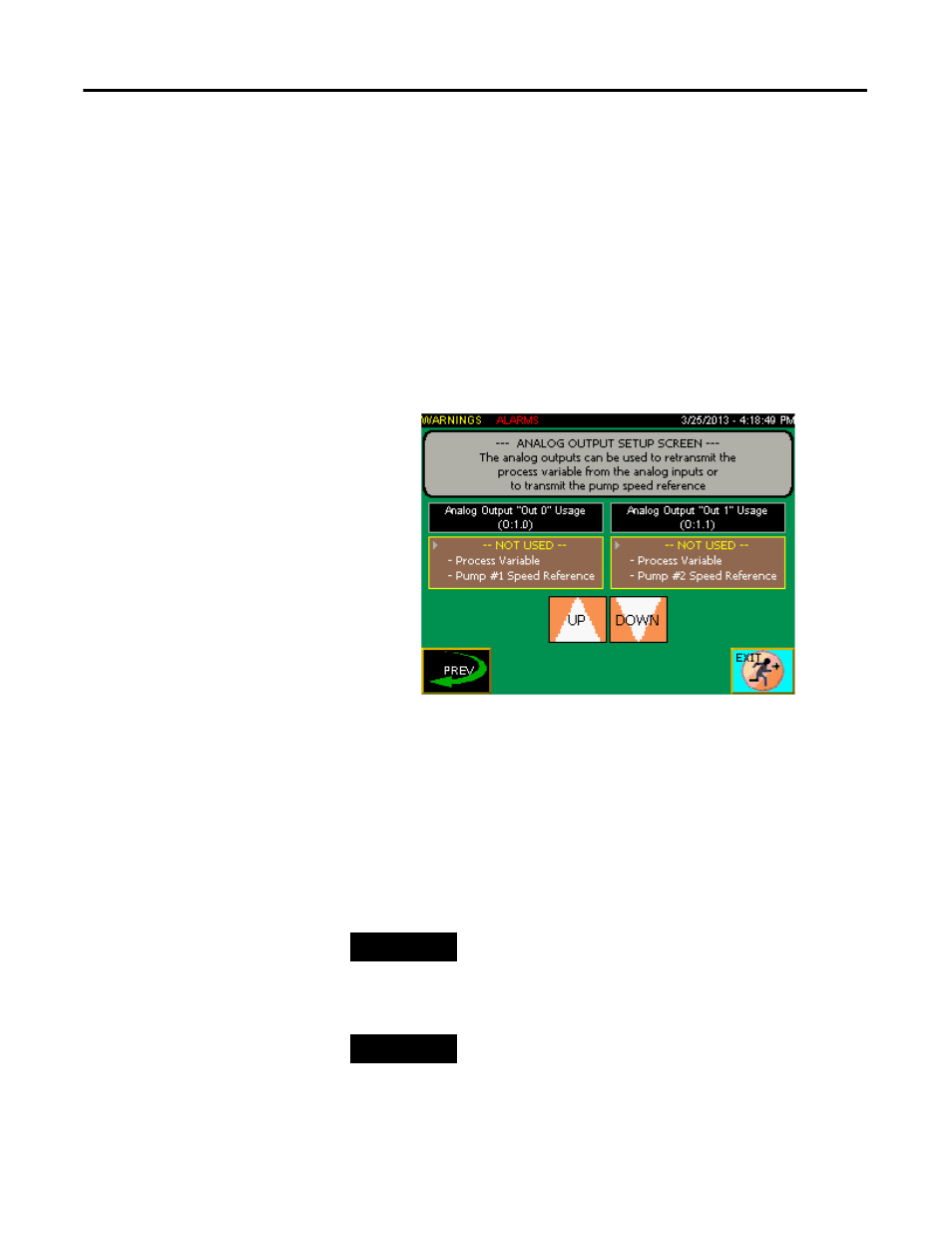
Configuring Analog Outputs
1. From the Main screen, press Analog Outputs Config to display the
configuration screen.
2. Set the Analog Output “Out 0” Usage (O:1.0) to retransmit a
4-20mA signal from the process variable (the analog signal connected to
one of the analog inputs) or to set the pump #1 VFD speed reference
(4mA=0Hz, 20mA=60Hz).
3. Set the Analog Output “Out 1” Usage (O:1.1) to retransmit a 4-20mA
signal from the process variable (the analog signal connected to one of
the analog inputs) or to set the pump #2 VFD speed reference
(4mA=0Hz, 20mA=60Hz).
TIP
Note: The process variable can be the signal from analog input I:1.0 or input I:1.1.
The default process variable is I:1.0 but can be changed from the Measuring
Setup screen under the Analog Input “In 1” Usage selection.
TIP
Note: In order for the analog output to transmit a VFD speed reference, the
corresponding pump needs to have either PowerFlex 4 series VFD or Other
VFD selected from the Motor Control Setup screen.