Rockwell Automation DC3N DC Drive User Guide, 1/4-2HP-115/230 VAC User Manual
Page 18
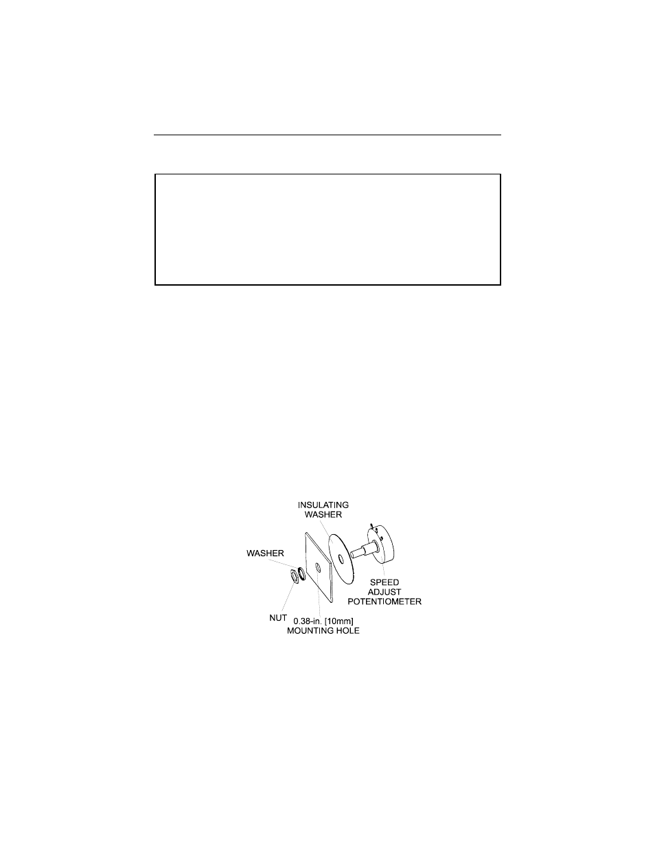
On the chassis drive, install the circular insulating disk between the panel and the
10K ohm speed adjust potentiometer. Mount the speed adjust potentiometer
through a 0.38 inch (10 mm) hole with the hardware provided (Figure 5). Twist the
speed adjust potentiometer wire to avoid picking up unwanted electrical noise. If
potentiometer leads are longer than 18 inch (457 mm), use shielded cable.
All enclosed controls come with the speed adjust potentiometer installed.
Alternate speed adjust potentiometer connections
Alternate speed adjust potentiometer connections may be found in the Application
Notes section of this user guide.
IMPORTANT:
The user may choose to install a 5K ohm speed adjust
potentiometer; however, the MIN SPD and MAX SPD trimpots must be
recalibrated if the 5K ohm potentiometer is used.
10
Installation
ATTENTION:
Because the reference potentiometer is connected through the
regulator to the armature power circuit, its terminals are at line potential. Use a
potentiometer that has a insulating shaft to insulate the operator knob from this
power circuit and that is capable of withstanding Hi-pot tests at 2000 Volts DC
for one minute. Failure to observe this precaution could result in severe bodily
injury or loss of life.
ATTENTION:
Be sure that the potentiometer tabs do not make contact with
the enclosure. Grounding the input will damage the drive.
ƽ
Speed adjust potentiometer
Figure 5. Speed Adjust Potentiometer Installation