Rockwell Automation 1786-series ControlNet Coax Media Planning and Installation Guide User Manual
Page 53
Publication CNET-IN002B-EN-P - June 2010
53
Install a ControlNet Coax Media System Chapter 3
4.
Lock the cable into place by moving the chamber-gauge ring forward
until it meets the cable with slight resistance, noting that the gauge:
•
moves two rollers toward the cable and regulates the depth of the cut.
•
clicks as it moves from one gauge to the next.
5.
Holding the cable in one hand, place the index finger of your other hand
inside the chamber-gauge ring and turn the strip tool 360 degrees
around the cable.
6.
Turn four or five full rotations until the strip tool glides easily around
the cable.
7.
Repeat steps 5 and 6, moving the chamber gauge ring forward one
notch for each time you repeat the steps until you reach the last notch,
noting that each time you move the chamber gauge ring forward a
notch, the strip tool makes a deeper cut into the cable.
8.
After you move the chamber gauge ring to the last position and turn the
strip tool the final time, complete these steps.
a. Move the chamber gauge ring backward to release the strip tool and
remove it from the cable.
b. If you are installing IP67 connectors, slide the heat shrink tubing over
the cable.
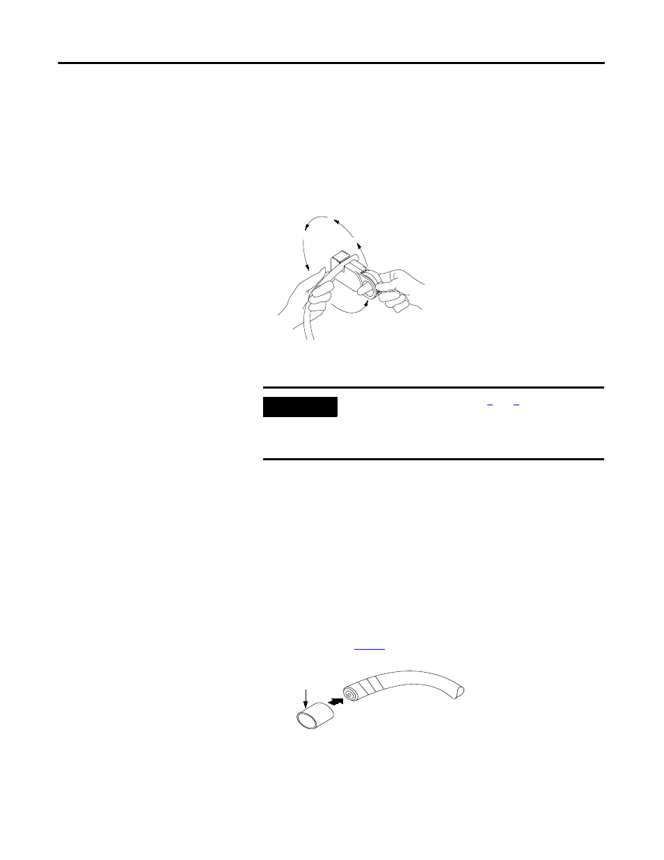
c. Slip the crimp
onto the cable, pushing it back to the sheath
area of the cable to keep it out of the way for the moment.
d. Strip away the appropriate portion of the cable without using the
strip tool.
e. Clean the remaining cable parts from the strip chamber after
each use.
IMPORTANT
On your last repetition of steps
, apply sufficient
pressure on the chamber gauge ring to make sure the ring
has reached the last stage. The chamber gauge should
read stop for the last repetition.
20074
41887a
Crimp Ferrule