Input power regulation – Rockwell Automation T8062 ICS Regent+Plus High Integrity Power Supply Assembly User Manual
Page 3
I/O Power Supply Assembly (T8060,T8062)
P D - 6 0 5 0 M a r - 0 6
3
The dual inputs on the AC modules are galvanically isolated from each
other. The inputs on the DC modules are diode isolated and share a
common return.
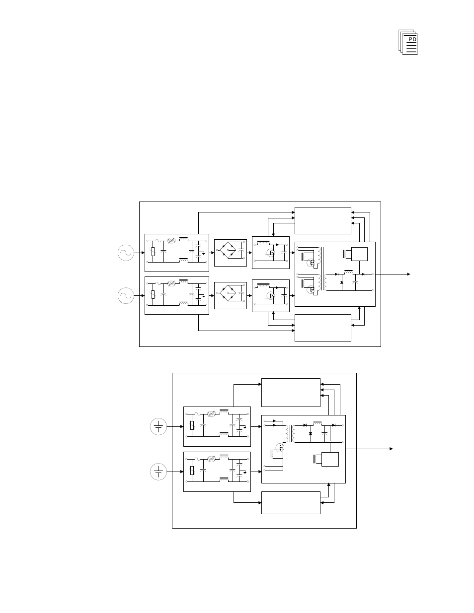
Input Power Regulation
A block diagram of a typical dual AC input I/O power supply module is
shown in Figure 2. A block diagram of a typical dual DC input I/O power
supply module is shown in Figure 3.
PFC
PFC
Power Supply Module
PWM
Switching Regulator
T1:a
T1:c
T1:b
Rectifier
Rectifier
DC
Output
I/P Filter & Protection
I/P Filter & Protection
PFC A Off
I/P A Fail
PFC A Fail
Source
A
Source
B
Fail
High Tempterature
Reset
O/P Current
Status & Control
Remote Off
PFC B Off
I/P B Fail
PFC B Fail
Status & Control
Figure 2. Block Diagram of an AC I/O Power Supply Module
Power Supply Module
DC
Output
I/P Filter & Protection
I/P Filter & Protection
PWM
Switching Regulator
T1:a
T1:b
I/P A Fail
Fail
High Tempterature
Reset
O/P Current
Status & Control
Remote Off
I/P B Fail
Status & Control
Source
A
Source
B
Figure3. Block Diagram of a DC I/O Power Supply Module.