Motor power and brake connector pinouts – Rockwell Automation 2093-AMxx Kinetix 2000 Integrated Axis Module and Axis Module Installation Instructions User Manual
Page 9
Kinetix 2000 Multi-axis Servo Drives 9
Rockwell Automation Publication 2093-IN001B-EN-P - July 2013
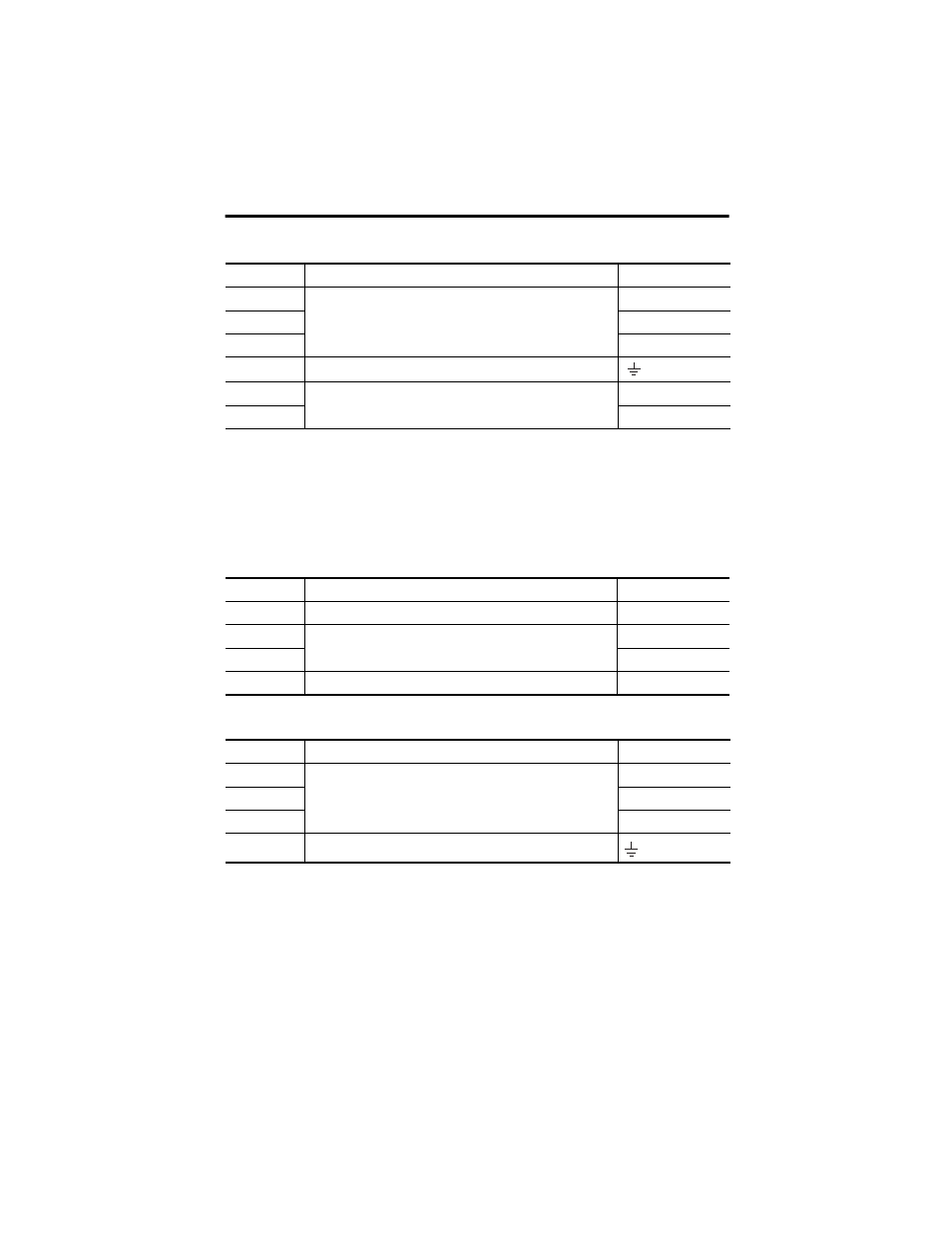
Main Power and DC Bus (IPD) Connector
Motor Power and Brake Connector Pinouts
These connectors are supplied with removable wiring plugs and are keyed to prevent incorrect
insertion. The pins are numbered consecutively from top to bottom.
Motor Brake Control (BC) Connector
Motor Power (MP) Connector
IPD Pin
Description
Signal
1
Single- or three-phase input power (230V AC)
L1
2 L2
3 L3
(1)
(1)
Not used with single-phase power.
4 Chassis
ground
5
An integral, unregulated power supply, consisting of AC line, three-phase bridge
rectifier, and filter capacitors
DC+
6 DC-
BC Pin
Description
Signal
1
+24V brake power (from LIM or customer supplied)
PWR
2
Motor brake connections
MBRK+
3 MBRK-
4
Motor brake common
COM
MP Pin
Description
Signal
1
Three-phase motor power
U
2
V
3
W
4
Chassis ground