Using the plc-5c processor – Rockwell Automation 1797-IRT8 FLEX Ex Thermocouple/RTD/mV Input Module User Manual User Manual
Page 76
Publication 1797-6.5.2 - February 2001
B-2 Programming the FLEX Ex I/O Modules Using RIO
Using the PLC-5C Processor
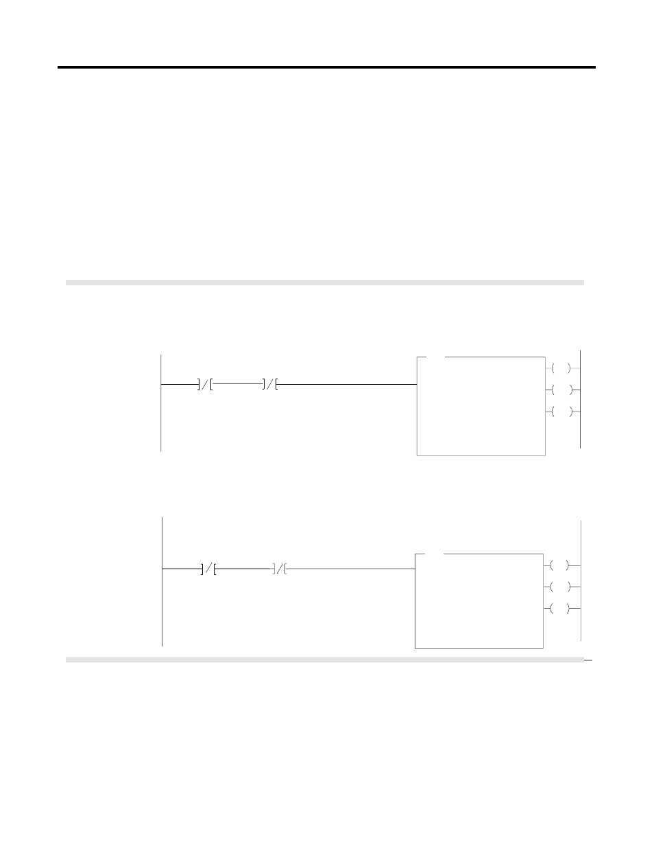
Block transfer instructions with the PLC-5C processor use a control file
and a data file. The block transfer control file contains the data table
section for module location, the address of the block transfer data file
and other related data. The block transfer data file stores data that
you want transferred to the module (when programming a BTW) or
from the module (when programming a BTR).
The programming terminal will automatically select the control file
based on rack, group and module, and whether it is a read or write.
A different block transfer control file is used for the read and
write instructions for your module. A different block transfer
control file is required for every module.
EN
BTR
BLOCK TRANSFER READ
Rack
Group
Slot
Control Block
14
1
0
BR141:0
DN
Data File
BT Length
Continuous
2BTD5:101
0
NO
ER
EN
BTW
BLOCK TRANSFER WRITE
Rack
Group
Slot
Control Block
14
1
0
BW141:0
DN
Data File
BT Length
Continuous
2BTD5:1
0
NO
ER
BR141:0
EN
BR141:0
EN
BW141:0
EN
Rung 1STEPO:1
The IRT8 module is located in rack 14, I/O group 1, slot 0. The data obtained by the PLC-5/250 processor from
the IRT8 module is placed in the data table starting at 2BTD5:101, and with the default length of 0, is 11 words
long. The length can be any number between 0 and 11.
BW141:0
EN
Rung 1STEPO:1
The IRT8 module is located in rack 14, I/O group 1, slot 0. The data sent to the IRT8 module from the PLC-5/250
processor is from the data table starting at 2BTD5:1, and with a default length of 0, is 4 words long.
Valid BTW lengths: 0, 1, 2, 3, and 4.
IRT8 BTR
Enable Bit
IRT8 BTW
Enable Bit
IRT8 BTR
Control File
IRT8 BTR
Enable Bit
IRT8 BTW
Enable Bit
IRT8 BTW
Control File
BT Timeout
4
BT Timeout
4
PLC-5/250 Processor
Program Example