Ce/cenelec i/o entity parameters – Rockwell Automation 1797-IRT8 FLEX Ex Thermocouple/RTD/mV Input Module User Manual User Manual
Page 68
Publication 1797-6.5.2 - February 2001
A-2 Specifications
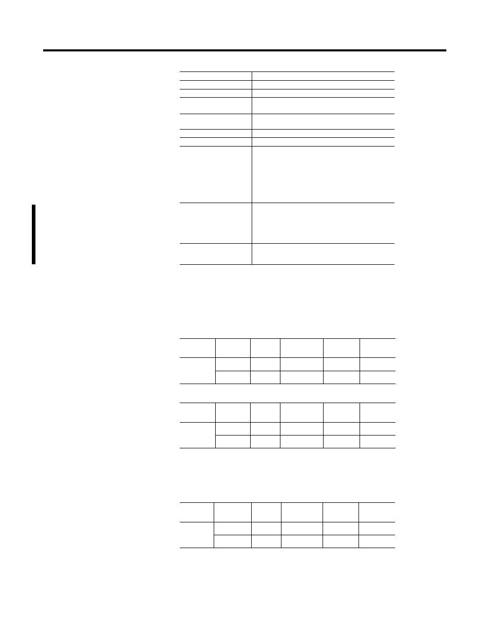
CE/CENELEC I/O Entity
Parameters
Input circuits (+ to -) for ch0 to ch7 (terminals: 0-3; 4-7; 8-11;
12-15; 17-20; 21-24; 25-28; 29-32)
CJC circuits (+ to -) for CJC0 and CJC1 (terminals: 37, 39; 46, 48)
Input circuits (+ to -) for ch0 to ch7 and CJC circuits (+ to -) for CJC0
and CJC1 (terminals 0-3, 37, 39; 4-7, 37, 39; 8-11, 37, 39; 12-15, 37, 39;
17-20, 37, 39; 21-24, 37, 39; 25-28, 37, 39; 29-32, 37, 39; 0-3, 46, 48;
4-7, 46, 48; 8-11, 46, 48; 12-15, 46, 48; 17-20, 46, 48; 21-14, 46, 48;
25-28, 46, 48; 29-32, 46, 48)
Power Dissipation
1.6W
Thermal Dissipation
Maximum 5.46BTU/hr
Module Location
Cat. No. 1797-TB3 or -TB3S Terminal Base Unit
Conductor Wire Size
12 gauge (4mm
2
) stranded maximum
3/64in (1.2mm) insulation maximum
Dimensions
46mm x 94mm x 75mm
(1.8in x 3.7in x 2.95in)
Weight
200g (approximate)
Keyswitch Position
2
Environmental Conditions
Operational Temperature
Storage Temperature
Relative Humidity
Shock
Operating
Nonoperating
Vibration
-20 to +70
o
C (-4 to +158
o
F)
-40 to +85
o
C (-40 to +185
o
F)
5 to 95% noncondensing
Tested to 15g peak acceleration, 11(+1)ms pulse width
Tested to 15g peak acceleration, 11(+1)ms pulse width
Tested 2g @ 10-500Hz per IEC68-2-6
Agency Certification
CENELEC
UL/C-UL
FM
II (1) 2G EEx ia/ib IIB/IIC T4
Class I Division 1 and 2 Groups A-D T4
Class I Zone 1 and 2 AEx ib/[ia] IIC T4
Class I Division 1 and 2 Groups A-D T4
Class I Zone 1 AEx ib/[ia] IIC T4
Certificate of Conformity
DMT 98 ATEX E 023 X
UL, C-UL Certificate Number 99.19699
FM Certificate Number 3009806
Protection
Group
Allowed
Capacitance
Allowed
Inductance
L
o
/R
o
Ratio
U
o
= 9V
I
o
= 37mA
P
o
= 83mW
EEx ia
IIB
40
µ
F
80mH
1.7mH/
Ω
EEx ia
IIC
4.9
µ
F
20mH
0.4mH/
Ω
Protection
Group
Allowed
Capacitance
Allowed
Inductance
L
o
/R
o
Ratio
U
o
= 9V
I
o
= 1mA
P
o
= 3mW
EEx ia
IIB
40
µ
F
1H
63mH/
Ω
EEx ia
IIC
4.9
µ
F
1H
15mH/
Ω
Protection
Group
Allowed
Capacitance
Allowed
Inductance
L
o
/R
o
Ratio
U
o
= 9V
I
o
= 38mA
P
o
= 86mW
EEx ia
IIB
40
µ
F
80mH
1.7mH/
Ω
EEx ia
IIC
4.9
µ
F
20mH
0.4mH/
Ω