Describing the controlnet ex system diagrams – Rockwell Automation 1797-BCNR FLEX Ex Redundant ControlNet Barrier Module User Manual
Page 14
14 FLEX Ex Redundant ControlNet Barrier Module
Publication
1797-5.35 - July 2004
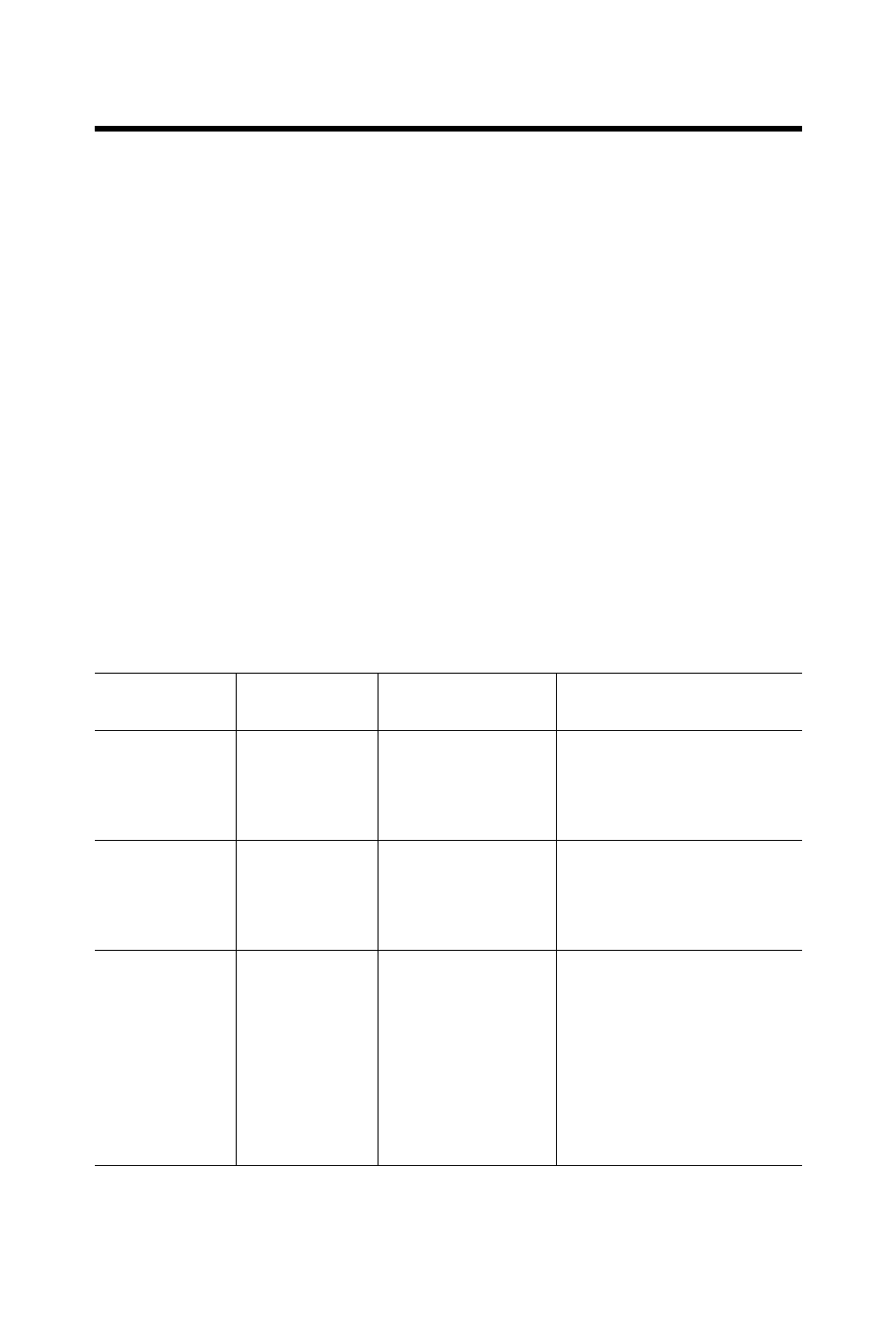
Describing the ControlNet Ex System Diagrams
A maximum of 48 ControlNet Ex
TM
nodes may be connected together by
250m of coax cable and 48 taps. The distance increases to 1000m when you
use only 2 taps. See the table below for more information.
The fiber media of the 1797-RPFM can be installed in a hazardous location
(Zone 0, 1 or 2; Class I, Zones 0, 1, and 2; Class I, Division 1 and 2; Class II,
Division 1 and 2; Class III, Division 1 and 2) to connect two 1797-RPFM
modules or they can be installed through different locations into the
non-hazardous location to connect the 1797-RPFM with any approved
associated apparatus.
All cables and fiber media that are not light blue must be marked as IS using
the 1797-EXMK marking kit or other locally approved IS identification
and/or segregation method.
During the installation of the ControlNet Ex system, all metallic parts must be
isolated to prevent an earth connection (high voltage withstanding of isolating
material must be > 500V ac).
System
Diagram Name
Catalog
Number
Catalog Name
Description
1797-RPA
1797-RPA
ControlNet Ex
Modular Repeater
Adapter
Represents one ControlNet Ex
node and must be connected
to a coax trunk cable by
1797-TPx
1797-RPFM
1797-RPFM
ControlNet Ex Fiber
Repeater Module,
Medium Distance
Allows connection of a
maximum of two devices per
1797-RPA and is powered
directly by 1797-RPA
1797-ACNR15
1797-ACNR15
Redundant Media
ControlNet Ex
Adapter
Represents one ControlNet Ex
node and must be connected
to a coax trunk cable by
1797-TPx -each one with two
redundant output channels
that are connected to different
ControlNet Ex networks (coax
cables and 1797-TPx)