0 programming, 1 register organization, 2 use in dcs 5000/automax systems – Rockwell Automation 61C501 AutoMax/AutoMate 115V Input Module User Manual
Page 15
4Ć1
4.0 PROGRAMMING
This section describes how data is organized in the module and
provides examples of how the module is accessed by the application
software. For more detailed information, refer to the Enhanced BASIC
Programming instruction manual (JĆ3675) for DCS 5000/ AutoMax
systems or the AutoMate 30/40 Software Reference instruction
manual (JĆ3150) for AutoMate systems.
4.1
Register Organization
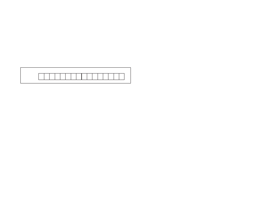
The data in the module is organized as one 16 bit register. The
software allows you to define the module as a single register (up to
16 bits) by referencing the entire module as a unit, or as up to 16
individual bits by treating each of the bits separately. Refer to figure
4.1.
register 0
R
0
1
2
3
4
5
6
7
8
9
10
11
12
13
14
15
R
R
R
R
R
R
R
R
R
R
R
R
R
R
R
(decimal)
Figure 4.1 Ć Organization of Register Bits
4.2
Use in DCS 5000/AutoMax Systems
This section describes how to use the module in DCS 5000/AutoMax
Systems.
4.2.1
Configuration
Before any application programs can be written, you must configure,
or set, the definitions of systemĆwide variables, i.e. those that must be
globally accessible to all tasks.
For DCS 5000 and AutoMax Version 2.1 and earlier, you define
systemĆwide variables by writing a Configuration task. For AutoMax
version 3.0 and later, you define systemĆwide variables using the
AutoMax Programming Executive. After these variables are defined,
you can generate the configuration file automatically, which
eliminates the requirement to write a configuration task for the rack. If
you are using AutoMax Version 2.1 or earlier, refer to Appendix E for
examples that show how to define variables in the configuration task.
If you are using AutoMax Version 3.0 or later, see the AutoMax
Programming Executive instruction manual for information about
configuring variables.