Rockwell Automation 61C351 2-In/2-Out 4-20 mA Analog Rail Module User Manual
Page 29
4Ć7
4.1.2
AutoMate Programming in Rail Mode
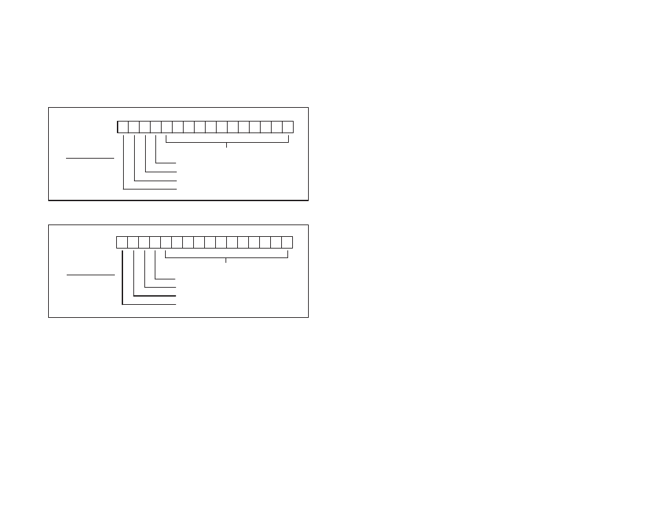
In Rail mode, the Analog Rail module is imaged in one I/O register of
the processor. Data from one of the four channels will occupy the
register as a function of the channel select bits. The active channel
is updated at the end of each scan. For input channels, the two
channel select bits in the register must be set to the appropriate
input channel number. After the I/O update, the register contains the
data in the format shown in figure 4.7. For output channels, the data
in the register must be in the format shown in figure 4.8 prior to the
I/O update.
17 16 15 14 13 12 11 10 7 6 5 4 3 2 1 0
Octal
12 bits of converted analog data
overĆrange (1=overĆrange)
underĆrange (1=underĆrange)
channel being read: LSB
channel being read: MSB
MSB LSB ăCH#
ă0ąą0 = CH 0
ă0ąą1 = CH 1
ă1ąą0 = CH 2
ă1ąą1 = CH 3
Figure 4.7 Ć Rail Mode Register Image for Input Channels
17 16 15 14 13 12 11 10 7 6 5 4 3 2 1 0
Octal
12 bits of analog output data
not used
not used
channel being modified: LSB
channel being modified: MSB
MSB LSB ăCH#
ă0ąą0 = CH 0
ă0ąą1 = CH 1
ă1ąą0 = CH 2
ă1ąą1 = CH 3
Figure 4.8 Ć Rail Mode Register Image for Output Channels
The Analog Rail module data may also be accessed in the middle of
the scan (as opposed to the end of the scan, which is the normal
mode of operation for digital rail I/O) using the appropriate number
of Analog In (AIN) and Analog Out (AOUT) blocks. The AIN block
will check whether the overĆrange or underĆrange bits have been set
by the module and the error coil will be energized, if applicable. The
AOUT block will set the channel select bits appropriately. See
section 4.1.4 for more information about the AIN and AOUT blocks.
Note that the AIN and AOUT blocks are supported by the AutoMate
20E M/N 45C224 and 45C225, but not the AutoMate 20 (M/N 45C20,
45C21, 45C220, 45C221) by APX Version 3.0.