Rockwell Automation 2094-xxxx Kinetix 6200 and Kinetix 6500 Control Module Installation Instructions User Manual
Page 7
Kinetix 6200 and Kinetix 6500 Control Modules 7
Rockwell Automation Publication 2094-IN012C-EN-P - August 2013
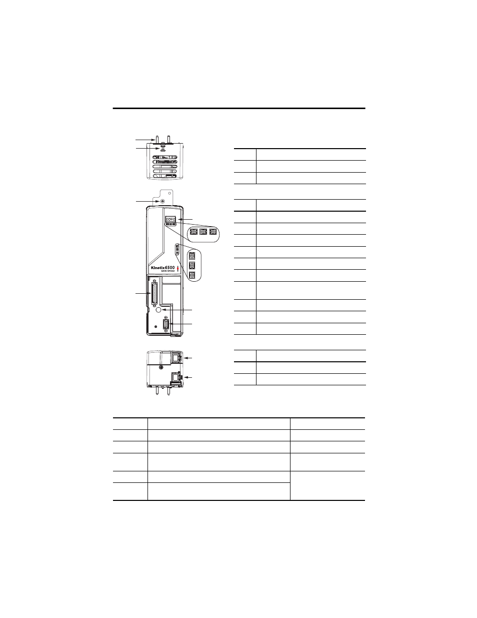
Kinetix 6500 Control Module Connectors and Indicators (Ethernet)
Kinetix 6200 and Kinetix 6500 Control Module Connectors
Designator
Description
Connector
IOD
User I/O (drive), safety, and auxiliary feedback
44-pin high-density D-shell
MF
Motor feedback
15-pin high-density D-shell
Tx and Rx
Sercos connections for controller programming
(only Kinetix 6200 modules)
Sercos fiber-optic (2x)
PORT1
Ethernet connection for safety configuration
RJ45
PORT2
Ethernet connection for controller programming
(only Kinetix 6500 modules)
2
3
2
7
4
5
6
1
10
12
11
13
9
8
14
Control Module (2094-EN02D-M01-S
x) Top View
Control Module (2094-EN02D-M01-S
x) Front View
Control Module (2094-EN02D-M01-S
x) Bottom View
Item
Description
1
Guide pins (2x)
2
Captive screw
Item
Description
3
Four-character status display
4
PORT 1 status indicator
5
PORT 2 status indicator
6
Module status indicator
7
Network status indicator
8
DC bus status indicator
9
Safety lock status indicator
(only 2094-EN02D-M01-S1 modules)
10
I/O, safety, and aux feedback (IOD) connector
11
Power module mounting screw access hole
12
Motor feedback (MF) connector
Item
Description
13
Ethernet (PORT1) connector
14
Ethernet (PORT2) connector