Feedback connector pinouts – Rockwell Automation 2094-xxxx Kinetix 6200 and Kinetix 6500 Control Module Installation Instructions User Manual
Page 10
10 Kinetix 6200 and Kinetix 6500 Control Modules
Rockwell Automation Publication 2094-IN012C-EN-P - August 2013
Feedback Connector Pinouts
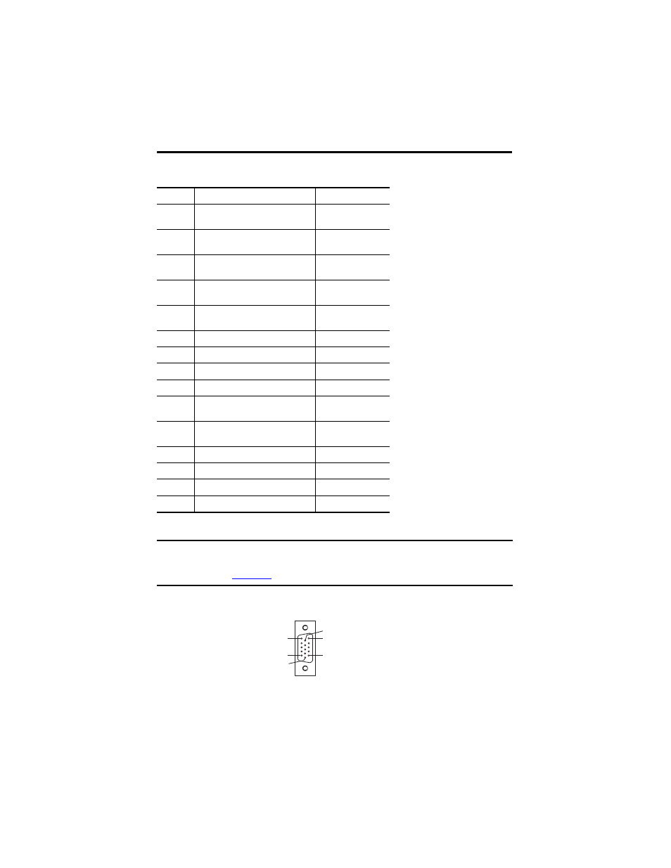
MF Connector Pin Orientation
MF Pin
Description
Signal
1
Sine differential input +
A differential input +
MTR_SIN+
MTR_A+
2
Sine differential input -
A differential input -
MTR_SIN-
MTR_A-
3
Cosine differential input +
B differential input +
MTR_COS+
MTR_B+
4
Cosine differential input -
B differential input -
MTR_COS-
MTR_B-
5
Data differential input/output +
Index differential input +
MTR_DATA+
MTR_I+
6
Encoder common
MTR_ECOM
7
Encoder 9V power output
MTR_EPWR9V
8
Hall commutation S3 input
MTR_S3
9
Clock output +
MTR_CLK+
10
Data differential input/output -
Index differential input -
MTR_DATA-
MTR_I-
11
Motor thermostat
(normally closed)
(1)
(1)
Not applicable unless motor has integrated thermal protection.
MTR_TS+
12
Hall commutation S1 input
MTR_S1
13
Hall commutation S2 input
MTR_S2
14
Encoder 5V power output
MTR_EPWR5V
15
Clock output -
MTR_CLK-
IMPORTANT
Drive-to-motor power cables must not exceed 90 m (295.5 ft). Additional limitations apply.
Refer to the Kinetix 6200 and Kinetix 6500 Modular Servo Drive User Manual, publication
, for more information.
Pin 11
Pin 6
Pin 15
Pin 1
Pin 10
Pin 5
15-pin Control Module
Motor Feedback (MF) Connector