Install the kinetix 7000 drive, Mount the kinetix 7000 drive – Rockwell Automation 2099-BMxxx Kinetix 7000 High Power Servo Drive Installation Instructions User Manual
Page 7
Kinetix 7000 High Power Servo Drives 7
Rockwell Automation Publication 2099-IN003B-EN-P - August 2013
Install the Kinetix 7000 Drive
These procedures assume you have prepared your panel, and understand how to bond your
system. For installation instructions regarding equipment and accessories not included here, refer
to the instructions that came with those products.
Mount the Kinetix 7000 Drive
Follow these steps to mount the drive.
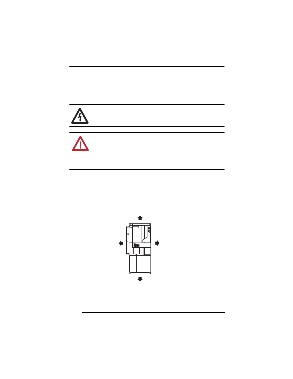
1. Observe these clearance requirements when mounting the drive to the panel.
SHOCK HAZARD: To avoid hazard of electrical shock, perform all mounting and wiring of the
Kinetix 7000 drive prior to applying power. Once power is applied, connector terminals can have
voltage present even when not in use.
ATTENTION: Plan the installation of your system so that you can perform all cutting, drilling,
tapping, and welding with the system removed from the enclosure. Because the system is of the
open type construction, be careful to keep any metal debris from falling into it. Metal debris or
other foreign matter can become lodged in the circuitry and result in damage to components.
ATTENTION: A sticker is affixed over the top vents on the drive. Remove this sticker after
installing the drive, and before applying power.
IMPORTANT
Mount the module in an upright position as shown. Do not mount the drive on its
side.
50.8 mm (2.0 in.) clearance
right of the drive.
101.6 mm (4.0 in.) clearance for
airflow and installation.
101.6 mm (4.0 in.) clearance for airflow
and cable installation.
50.8 mm (2.0 in.) clearance
left of the drive.
Minimum cabinet depth = 300 mm (11.8 in.).
Cable bend radius requires a minimum of
60 mm (2.4 in.) from the front panel connections.