Rockwell Automation 2099-BMxxx Kinetix 7000 High Power Servo Drive Installation Instructions User Manual
Page 14
14 Kinetix 7000 High Power Servo Drives
Rockwell Automation Publication 2099-IN003B-EN-P - August 2013
Motor and Auxiliary Feedback Connector Pinout
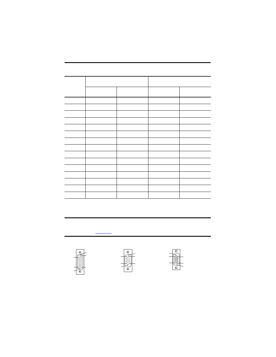
IOD, MF, and AF Connector Pin Orientation
MF Pin
Motor Feedback
(MF connector)
Auxiliary Feedback
(1)
(AF Connector)
(1)
For TTL devices, the position count increases when A leads B. For sinusoidal devices, the position count increases when cosine leads sine.
Stegmann
(SRS/SRM)
TTL or
Sine/Cosine
(2)
(2)
Encoder is incremental with index pulse and Hall commutation.
Stegmann
TTL or
Sine/Cosine
1
SIN+
A+ / SIN+
SIN+
A+ / SIN+
2
SIN-
A- / SIN-
SIN-
A- / SIN-
3
COS+
B+ / COS+
COS+
B+ / COS+
4
COS-
B- / COS-
COS-
B- / COS-
5 DATA+
IM+
DATA+
I+
6
ECOM ECOM ECOM ECOM
7 EPWR_9V
(3)
(3)
Encoder power supply uses either 5V DC or 9V DC based on encoder/motor combination.
EPWR_9V
(3)
EPWR_9V
(3)
EPWR_9V
(3)
8 –
S3
–
–
9
– – – –
10
DATA- IM- DATA- I-
11
TS TS – –
12 –
S1
–
–
13 –
S2
–
–
14 EPWR_5V
(3)
EPWR_5V
(3)
EPWR_5V
(3)
EPWR_5V
(3)
15
—
– – –
IMPORTANT
Combined motor power/feedback cable length must not exceed 90 m (295.2 ft). Additional
limitations apply. Refer to the Kinetix 7000 Multi-axis Servo Drive User Manual, publication
, for more information.
Pin 18
Pin 26
Pin 1
Pin 9
Pin 10
Pin 19
26-pin I/O (IOD)
Connector
Pin 11
Pin 6
Pin 15
Pin 1
Pin 10
Pin 5
15-pin Motor
Feedback (MF)
Connector
Pin 1
Pin 11
Pin 10
Pin 5
Pin 6
Pin 15
15-pin Auxiliary
Feedback (AF)
Connector