Hf bonding your shunt module, Establishing noise zones – Rockwell Automation 2090-SRxxx External Shunt Modules Installation Instructions User Manual
Page 6
Publication 2090-IN004B-EN-P — June 2008
6 External Shunt Modules
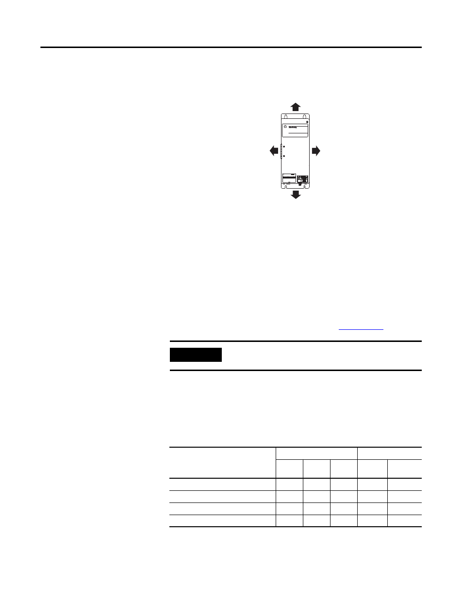
Minimum Clearance Requirements (outside the enclosure)
HF Bonding Your Shunt Module
Bonding is the practice of connecting metal chassis, assemblies,
frames, shields, and enclosures to reduce the effects of
electromagnetic interference (EMI). For more information on the
concept of high-frequency (HF) bonding, the ground plane principle,
and electrical noise reduction, refer to System Design for Control of
Electrical Noise Reference Manual, publicatio
.
Establishing Noise Zones
This table provides the zoning requirements of cables connecting to
the external shunt module.
1394 Digital Servo Controller
3600W Shunt Module
BULLETIN 1394 3600W SHUNT MODULE
ALLEN-BRADLEY
FOR USE WITH 1394-SJT22-X SYSTEM MODULE
CAT.
PART
SER.
INPUT DC
INPUT AC
FOR FUSE REPLACEMENT USE:
BUSSMAN CAT. NO.
R
150 mm (6.0 in.) clearance
for airflow and installation.
150 mm (6.0 in.) clearance
for airflow and installation.
150 mm (6.0 in.) clearance
for airflow and installation.
254 mm (10.0 in.) clearance
for airflow and installation.
Bulletin 1394 and 2090
External Shunt Modules
(1394-SR36Ax module is
shown in this example.)
IMPORTANT
To improve the bond between the drive system and subpanel,
construct your subpanel out of zinc plated (paint-free) steel.
Wire/Cable
Zone
Method
Very
Dirty
Dirty
Clean
Ferrite
Sleeve
Shielded
Cable
COL, DC+ (shielded option)
X
X
COL, DC+ (unshielded option)
X
Thermal switch
X
X
Fan (if present)
X