Wire the external shunt module – Rockwell Automation 2090-SRxxx External Shunt Modules Installation Instructions User Manual
Page 15
Publication 2090-IN004B-EN-P — June 2008
External Shunt Modules 15
Wire the External Shunt Module
This section assumes you have mounted your external shunt module
and are ready to wire the shunt module power connections.
on
page 22
for the servo drive user
manual with the drive-end installation instructions.
Wire should be copper with 105
°
C (221
°
F) 600V minimum rating.
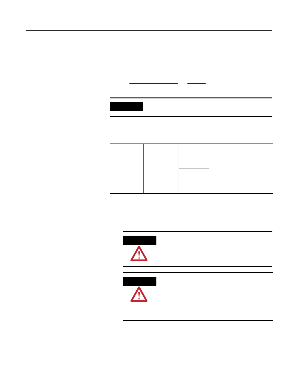
DC-bus Wiring Requirements
Follow these steps to wire your external shunt module.
1. Remove power from your drive system that includes the Bulletin
1394 or 2090 shunt module.
IMPORTANT
The National Electrical Code and local electrical codes take
precedence over the values and methods provided.
External Shunt
Cat. No.
Drive Module
Cat. No.
Shunt Module
Terminal
Connections
Recommended
Wire Size
mm
2
(AWG)
Torque Value
N•m (lb•in)
2090-SRxxx-xx
2098-xxx-HV030
2098-xxx-HV050
2098-xxx-HV100
COL
6 (10)
1.25 (11)
DC+
1394-SR9Ax,
1394-SR36Ax
2094-BSP2
1394x-SJT22-x
COL
8.4 (8)
2.5 (22.1)
DC+
ATTENTION
This system may have multiple sources of power. More than
one disconnect switch may be required to de-energize the
system. To avoid shock hazard or personal injury, verify that all
power has been removed before proceeding.
ATTENTION
This product contains stored energy devices. To avoid hazard
of electrical shock, verify that all voltage on the capacitors has
been discharged before attempting to service, repair, or
remove this unit. You should only attempt the procedures in
this document if you are qualified to do so and familiar with
solid-state control equipment and the safety procedures in
publication NFPA 70E.