Rockwell Automation 2090-SRxxx External Shunt Modules Installation Instructions User Manual
Page 5
Publication 2090-IN004B-EN-P — June 2008
External Shunt Modules 5
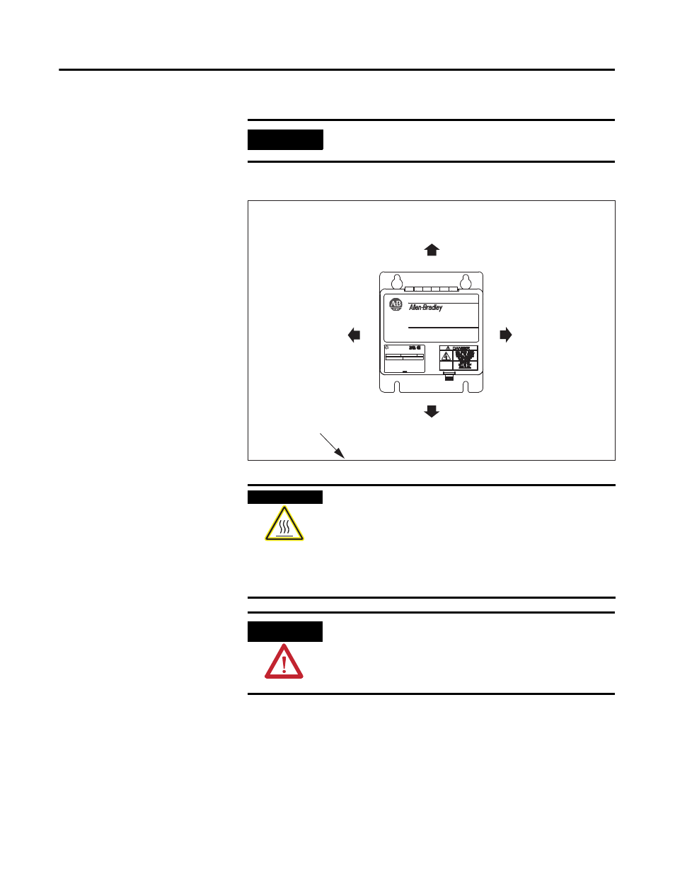
Minimum Clearance Requirements (within an enclosure)
IMPORTANT
Mount the shunt module in an upright position. Do not mount the
shunt module on its side.
BULLETIN 1394 300W SHUNT MODULE
ALLEN-BRADLEY
FOR USE WITH 1394-SJT22-X SYSTEM MODULE
CAT.
PART
SER.
INPUT DC
INPUT AC
FOR FUSE REPLACEMENT USE:
BUSSMAN CAT. NO.
R
Shunt Module
150 mm (6.0 in.) clearance
for airflow and installation.
150 mm (6.0 in.) clearance
for airflow and installation.
150 mm (6.0 in.) clearance
for airflow and installation.
150 mm (6.0 in.) clearance
for airflow and installation.
Enclosure
Bulletin 1394 and 2090
External Shunt Modules
(1394-SR9Ax module is
shown in this example.)
BURN HAZARD
The shunt resistors can reach temperatures in excess of 350
°
C
(662
°
F). Do not handle a shunt module that has been operational until
it has cooled sufficiently.
Combustible materials above the shunt module or its enclosure may
need the protection of a metal plate to shield them from the heat.
Failure to observe these precautions could result in damage to
surrounding materials, possibly leading to a fire or personal injury.
ATTENTION
The shunt resistors release large amounts of heat. When mounted
inside an enclosure, you must provide adequate ventilation so the
maximum ambient temperature of 50
°
C (122
°
F) is not exceeded.
Failure to observe this precaution could result in damage to the
module.